
The controller uses the quality of client signal levels reported by the APs to determine if the power level of that AP needs to be increased. Coverage Hole Detection (CHD) is controller independent, so RF group leader is not involved in those calculations.
If clients SNR drops below the configured threshold value on the controller, the AP increases its power level to try to compensate for the client. The SNR threshold is based on the transmit power of the AP and the coverage profile settings on the controller.
The controller uses the following equation for detecting a coverage hole:
Client SNR Cutoff Value |dB| =[ AP Transmit Power (dBm) – Constant (17dBm) – Coverage Profile(dB) ]
Depending on the number of clients that are at or below this value for longer than 60s, coverage hole correction might be triggered & AP could increase power level to try to remove the SNR violation.
By default Coverage Hole Detection is enabled. You can change the settings in “Wireless -> 802.11a or 802.11b -> RRM -> Coverage” section.
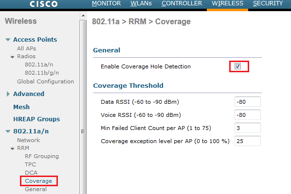
You can set different threshold RSSI values for Data & Voice clients. If an AP receives a packet in the data/voice queue with an RSSI value below configured threshold, a potential coverage hole has been detected. The AP take data/voice clients RSSI measurement in every 5s & reports them to WLC in every 90s interval.
In “Min Failed Client Count per AP” you can enter the minimum number of clients on an AP with RSSI value at or below the data/voice RSSI threshold. Default value is 3.
In the Coverage Exception Level, enter the % of clients on an AP that are experiencing a low signal level but cannot roam to another access point. Default value is 25%
Should the number and the percentage of failed packets exceed the value configured for “Failed Packet Count” & “Failed Packet Percentage” (configurable via CLI only) for 5s, the client is considered to be in a pre-alarm condition. The controller uses this information to distinguish between real & false coverage holes
config advanced 802.11a coverage data|voice packet-count 20 <- default 10 [1-255]
config advanced 802.11a coverage data|voice fail-percentage 25 <-default 20%
In the above, first command sets minimum failure count threshold for uplink data or voice packets. Second line sets a failure rate threshold for uplink data or voice packets.
You can use “show advanced 802.11a|802.11b coverage” CLI commands to see the parameters settings in CHD.
(WLC1) >show advanced 802.11a coverage
Coverage Hole Detection
  802.11a Coverage Hole Detection Mode........... Enabled
  802.11a Coverage Voice Packet Count............ 100 packets
  802.11a Coverage Voice Packet Percentage....... 50%
  802.11a Coverage Voice RSSI Threshold.......... -80 dBm
  802.11a Coverage Data Packet Count............. 20 packets
  802.11a Coverage Data Packet Percentage........ 25%
  802.11a Coverage Data RSSI Threshold........... -80 dBm
  802.11a Global coverage exception level........ 25 %
  802.11a Global client minimum exception lev.... 3 clients
We can enable/disable for a given WLAN as well. Under WLAN advanced settings you can see an option to enable or disable CHD.

Related Posts
1. RRM Basics
2. Configuring RRM
3. Configuring DCA
4. Configuring TPC
5. Configuring ClientLink
6. Override RRM
7.
8. Rogue Access Point Detection

Hi Rasika!
As you now i’m working with WLC version 7.6.100, and i see in 802.11a global parameters a new configurable value: RSSI Threshold (-60 to -90 dBm), the default value is -80.
I don’t know if this value is regarding coverage hole, because is under global parameters not under coverage, i’m not able to find in Cisco 7.6 configuration guide the purpose of this field.
I will try to find out whats the function of this value.
Regards!
How can i see the CHD report in controller