
How do you manage allocating IP subnets for wireless clients where client numbers are rapidly growing over the time ? In my campus environment every year when students start their academic semester, we noticed few wireless subnets hits its capacity & had to increase the subnet size or add new subnets. But even doing this, cannot guaranteed we would have enough IPs in a given subnet. When users concentrate into particular geographical area depend on the time of the day, certain subnets will over utilized where other subnets are under utilized.
What’s the proper solution for this sort of issue ? Cisco introduced a feature called “VLAN Select” in WLC software release 7.0.116.0 where we can combine multiple interfaces in to a single pool. In this way clients would get IPs in round-robin fashion where all interfaces will approximately equally utilized. In this way we can have different size of subnets (in my campus environment we have /21, /22, /23, /24) without worried about how to control number of clients connects to each vlans.
In software 7.0.116.0 release, a round-robin algorithm used to load balane clients into different subnets. This results a new IP address to a client even when client is re-associating & thus depleting IP addresses faster. Refer Cisco Doc 112932 for more detail of “VLAN Select Deployment Guide” for software release 7.0.116.0 which is in the current CCIE wireless v2.0 lab exam.
In software release 7.2 onwards (only for the newer controller 5508, WiSM2, 7500, 2500) Cisco has modified the algorithm to based on client’s MAC address. In order to support this feature in legacy controllers (44xx series) cisco introduced this to 7.0.230.0 release where it can run on 44xx platforms. Refer Cisco Doc 113465 for more detail of “VLAN Select Deployment Guide” in software release 7.2 onwards. This is how modified algorithm works.
1. When a client associates to a WLAN on a controller, an index is calculated based on the MAC address of client & the number of interfaces in the interface group using a hash algorithm.
2. Based on this index, an interface is assigned to the client
3. Whenever this client joins the controller, the hashing algorithm always returns the same index and client is assigned to the same interface.
4. If index is “dirty” then a random index is generated and the interface is assigned based on the random index.
5. If that interface is still “dirty” then a fallback to round robin implementation occurs.
This feature adds a challenge to optimize multicast traffic in wireless world. Once we enable “VLAN Select” feature it will allow clients of a given WLAN to get IPs from multiple dynamic interfaces (in legacy mode given WLAN will allocate single dynamic interface IPs to its clients). Therefore when a given WLAN clients want to receive a multicast stream, each interface on the vlan pool join to multicast group individually (ie Multiple MGIDs for same group). To avoid this “Multicast VLAN Feature” included where you can select a single interface to represent multicast traffic for all the dynamic interfaces in same vlan pool.
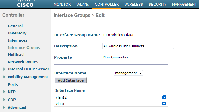
In the following section, I have described how to enable this feature on a WLC (I am running on 7.0.116 code on 4402 in my lab set up). First you need to create a interface group (Controller > Interface Groups)
Then you need to add interfaces to your interface group. In my case I have added 2 dynamic interfaces (Vlan 12 10.10.12.0/24 & Vlan 14 – 10.10.14.0/24) into this group.
Final step is to assign this interface group into your WLAN where client get associated. In my example I have assigned this to WLAN ID# 2 (MRN-VOIP).
Now you can test with client association & ensure clients are getting IPs from both subnet when they join the WLAN.
(WLC1) >show client summary
Number of Clients................................ 5
MAC Address       AP Name           Status        WLAN/GLAN      Auth Protocol         Port Wired
----------------- ----------------- ------------- -------------- ---- ---------------- ---- -----
00:1b:d4:58:e6:1a HQ-AP01           Associated    2              Yes  802.11a          1    No
00:22:fa:94:68:58 HQ-AP01           Associated    2              Yes  802.11a          1    No
04:f7:e4:ea:5b:66 HQ-AP01           Associated    2              Yes  802.11n(5 GHz)   1    No
64:20:0c:e0:23:75 HQ-AP01           Associated    2              Yes  802.11n(5 GHz)   1    No
a0:88:b4:35:c2:f0 HQ-AP01           Associated    2              Yes  802.11n(5 GHz)   1    No
20:02:af:12:e4:f7 HQ-AP01           Associated    2              Yes  802.11n(5 GHz)   1    No

(WLC1) >show client detail 00:1b:d4:58:e6:1a
Client MAC Address............................... 00:1b:d4:58:e6:1a
AP MAC Address................................... a0:cf:5b:9e:e8:20
AP Name.......................................... HQ-AP01
Client State..................................... Associated
Wireless LAN Id.................................. 2
BSSID............................................ a0:cf:5b:9e:e8:2e
IP Address....................................... 10.10.14.51

(WLC1) >show client detail 00:22:fa:94:68:58
Client MAC Address............................... 00:22:fa:94:68:58
AP MAC Address................................... a0:cf:5b:9e:e8:20
AP Name.......................................... HQ-AP01
Client State..................................... Associated
Wireless LAN Id.................................. 2
BSSID............................................ a0:cf:5b:9e:e8:2e
IP Address....................................... 10.10.12.54

(WLC1) >show client detail 04:f7:e4:ea:5b:66
Client MAC Address............................... 04:f7:e4:ea:5b:66
AP MAC Address................................... a0:cf:5b:9e:e8:20
AP Name.......................................... HQ-AP01
Client State..................................... Associated
Wireless LAN Id.................................. 2
BSSID............................................ a0:cf:5b:9e:e8:2e
IP Address....................................... 10.10.12.52

(WLC1) >show client detail 64:20:0c:e0:23:75
Client MAC Address............................... 64:20:0c:e0:23:75
AP MAC Address................................... a0:cf:5b:9e:e8:20
AP Name.......................................... HQ-AP01
Client State..................................... Associated
Wireless LAN Id.................................. 2
BSSID............................................ a0:cf:5b:9e:e8:2e
IP Address....................................... 10.10.14.55

(WLC1) >show client detail a0:88:b4:35:c2:f0
Client MAC Address............................... a0:88:b4:35:c2:f0
AP MAC Address................................... a0:cf:5b:9e:e8:20
AP Name.......................................... HQ-AP01
Client State..................................... Associated
Wireless LAN Id.................................. 2
BSSID............................................ a0:cf:5b:9e:e8:2e
IP Address....................................... 10.10.12.53

(WLC1) >show client detail 20:02:af:12:e4:f7
Client MAC Address............................... 20:02:af:12:e4:f7
AP MAC Address................................... a0:cf:5b:9e:e8:20
AP Name.......................................... HQ-AP01
Client State..................................... Associated
Wireless LAN Id.................................. 2
BSSID............................................ a0:cf:5b:9e:e8:2e
IP Address....................................... 10.10.14.56
As you can see clients are distributed evenly in subnet 12 & 14 as we expected. Now if you look at multicast groups (Monitor > Multicast ) to see how multicast traffic handle by the WLC. I have used multicast group address 239.255.255.199 to stream a video to wireless clients.
As you can see, there are two MGID for the each multicast group (one for Vlan 12 & one for Vlan 14). If my interface group have 10 dynamic interfaces, I should see 10 different MGID for the same multicast group address. To remove this inefficiency (duplicate stream for same wlan associated interfaces) you can enable “multicast vlan” feature under WLAN. I have selected vlan 12 as multicast vlan for this interface group.
Once you do this, you will only see vlan 12 in the MGID list. Therefore there won’t be multiple copies of multicast traffic for each vlan on same interface group. (See below)

Similar to layer 3 multicast as shown in the above, layer 2 multicast/broadcast optimization also important with this “VLAN select” feature. Additional CLI commands were introduced in 7.0.116.0 onwards to optimize layer 2 multicast & broadcast. L2 multicast/broadcast uses L2 MGID to forward the packets to AP. L2 multicast/broadcast from all the VLANs in the group will be sent on WLAN. This causes duplication packets on air. In order to limit these duplicate L2 multicast/broadcast enabling or disabling per interface is introduced. You can use following CLI command on newer controller (5508,2500, 7500 & WiSM-2). Since I have 4402 in my lab I could not able to test this feature at this time.
<WLC> config network multicast l2mcast <enable|disable> <interface-name>
Note that GUI support is not yet introduced for this L2 multicast feature.

Hi Rasika,
Can I use Multicast VLAN feature if I do not have interface groups in the WLC?. We have AP groups with the global SSID’s (staff, student, etc) assigned to specific interface/vlan on that AP Group.
On the other hand, I think that this feature does not apply if you are using mDNS. Please let me know your opinion about this.
thanks
Hi,
Multicast vlan feature select a single dynamic interface for multicast communication, if you have pool multiple dynamic interface map to single SSID. So it is only useful if you have interface group defined. If you have single dynamic interface for SSID, then it will be used for all communication.
mDNS is different, it is only applicable for link local multicast traffic (which is TTL=1).
HTH
Rasika
I’m trying to assign different interfaces/vlans to AP groups, but all under the same Vlan. However, when i test, it seems to default to the configured default interface for the WLAN, and not the override interface as per AP Group. Any thoughts on why this is happening?
Makesure you move the AP to the AP-Group. Always AP group configuration take precedance over wlan configuration
HTH
Rasika
Thanks for the great information. I have a question. I have a customer that wants to use the management interface for all SSID’s on different VLAN’s and they also want to FlexConnect all SSIDs based on FlexConnect and AP groups. So, I’ve got that part figured out. However, they also want to do VLAN Select to round robin clients on different VLAN’s. Is that possible given the above configuration?
Using management interface for SSID is not advisable (not a best practice). Create a dummy vlan if you want to assign something to the SSID by default & then use FlexConnect vlan mapping to assign the correct dynamic interface.
With FlexConnect local switching, I do not think you can have vlan pooling/ or interface group feature.
HTH
Rasika
Hi, hope you are doing fine, please can one AP CONFIGURED TO SUPPORT MULTIPLE ssid ,im using cisco AIR-CAP3702I-A-K9, thanks in advance.
Yes, if autonomous, each SSID should map to unique vlan.
HTH
Rasika
A word of warning about “VLAN Select” that can cause DHCP scope exhaustion, and prevent devices from associating…(and a lot of pain to troubleshoot)
The WLC monitors DHCP requests/responses to determine whether the server is functional. Typically clients issue a DHCP request, wait for a period (up to 30s), then send another request if necessary. Some Android clients will spam out a large number of requests (multiple requests per second), and if the WLC loses track of responses (or the DHCP Server simply doesn’t respond to all of them), it will mark the interface as dirty.
Now, if a client that was previously on that VLAN goes away for a period, then returns (laptop suspend, phone goes out for lunch, etc), the WLC may not be able place the client into the same VLAN that it was in (as it is now dirty), so it puts it into the next VLAN (calculated by MAC HASH). The user now has 2 DHCP leases – one in the old, and one in the new subnet.
This cycle continues to occur until the WLC has all VLANs marked as dirty, at which point it unmarks the oldest dirty interface, and places the next client into it. The issue escalates to a point where all scopes have been consumed, and all interfaces (bar one) become marked as dirty. No new client can connect, and only returning clients who are fortunate enough to have an existing DHCP lease in the VLAN they wind up in will work.
I have observed this behaviour at several sites using this feature. the one I spent the most time on had 6 x /24’s and approx 350 clients connecting. All at one site, spread over 3 floors. DHCP Lease was 4 hours, dropped to 1 hour and the issue still occurred. I was regularly seeing clients with up to 4 or 5 leases (one in each subnet).
One bad client will be tolerated, but when there are many, the issue shows itself. It wouldn’t happen daily, but was occurring a couple of times a week. Tried adding another 2x /24’s, issue kept happening. Eventually I made one large subnet, and haven’t seen it again.
Another customer with the issue had 3 remote mining camps, each with a WLC using interface groups. 500 miners would show up and connect with every device they had, and cause the same issue…
There are plenty of others who have experienced the issues, have a search on Google… Long story short, in most cases Broadcast traffic not forwarded on a WLAN, so you can use large client subnets… /21 should be fine, /20 also should be fine. If these arent big enough, use AP Groups, and configure different VLANs per group (for a given SSID)
Thanks for the update Tim, may be useful to others
Rasika
Does multicast have to be enabled on the wired side for VLAN select to work.
No, VLAN select does not have any dependancy on multicast.
However if you want to efficient multicast on vlan select enable WLAN, then you will pick one interface out of the pool for multicast query for given WLAN
HTH
Rasika
We also use VLAN Select but understand VLAN Select is not compatible with IPv6 so we are going back to Cisco to see what the largest subnet is that they think we can support as a single interface. (We would like to do a single /16 to support the client capacity of an 8510). Thoughts?
As long as you keep ” broadcast suppress” do not think a huge issue.
HTH
Rasika
Is there a way to use an interface group and then have something outside like Microsoft NPS assign AD users to a specific subnet based on their OU?
It is a sorta complicated way to seperate users that can have internal access and users that can’t. The problem is trying to do this with one SSID. Then after they connect, use NPS to change them to a different subnet with restricted rules if they are not allowed internal access, or let them stay on the subnet that has access to the internal network. Again, this is all based on what OU they are a part of in AD.
The easy solution would probably be to just use different SSIDs for the different groups of users and have the users attach the SSID they are given access to and then put a restricting ACL on the subnet.
Thanks,
Robby
Yes, this is possible, Feature is called AAA override.
You can use the same SSID, once client get authenticated, addition to RADIUS-ACCEPT, it can provide interface or interface group that client should assign. In that way you can override default interface WLAN map to, based on user_id OU.
In our network staff & students are placed onto different network using same SSID.
HTH
Rasika
Thanks for the information. Assuming I have 4 interfaces part of the group, global MC configured (no video/media feature). The WLC will send the MC down to the APs (as they joined the MC tree). It will send only one copy (obviously, as this is multicast). What I do not understand (if i do not use the MC VLAN feature) – I have now 4 MGIDs (4 clients in each VLAN joined the same MC group) – but why do I now have multiple .11 MC copies in the air? It would be enough to send one .11 frame in the air (regardless if I have the MC VLAN feature enabled or not). Is the number of MGIDs equal to the numbers of MC copies in the air?
My understanding is VLAN select feature prevent AP to send IGMP Membership Report to upstream for all those interfaces. Once you nominate one vlan, that will send Membership Rerport on behalf of all other vlans.
HTH
Rasika
Thanks. Indeed. If we have 2 MGIDs, we have two IGMP joins. We will get the traffic for MC group A within both VLANs. But as the SSID covers multiple VLANs, we need the traffic only once and we send a .11 multicast within the SSID which will reach clients that are assigned to different VLANs. The reason is that we do not have a 1 VLAN to 1 SSID mapping, but a e.g. 2 VLANs (within a group) to one SSID mapping. The same MC group has to be delivered only once to the WLC to be forwarded to the AP via MC and later to be broadcasted there as a .11 MC frame.
Have a great weekend,
Robert