
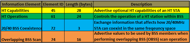
802.11n introduces 4 new information elements which can be seen in 802.11n (HT) beacon frames.
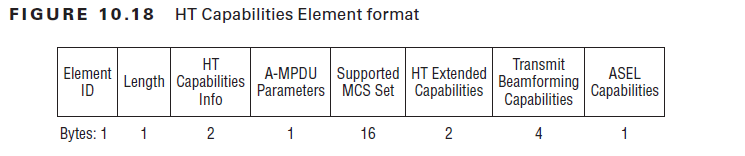
 HT STAs declare themselves as HT STA by transmission of HT Capabilities Element in Beacon, Probe Request, Probe Response, Association Request, Association Response, Reassociation Request & Reassociation Response frames. Below diagram shows the format of HT Capabilities Information Element.(page 383- CWAP Official Study Guide)
 Here is a Beacon frame capture shows these filed of HT capabilities IE.
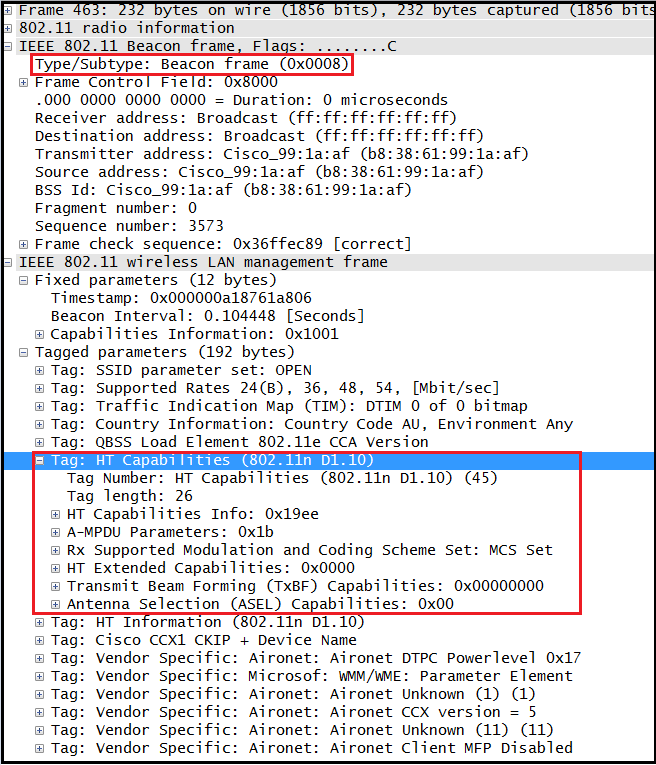 1. Element ID (1 byte)
This is 45 for this information element.
2. Length (1 byte)
Length field value is 26 indicating 26 bytes follows the content of this information element.
3. HT Capabilities Info (2 bytes)
Below diagram shows the format of this field.(page 384 – CWAP Study Guide)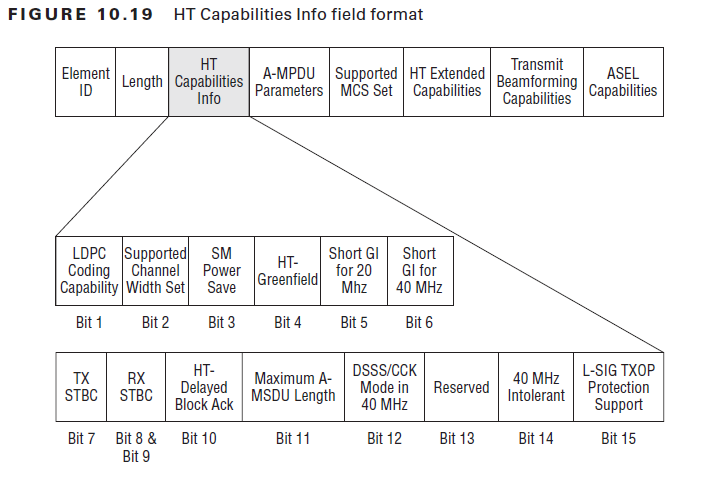 Here is a frame capture showing these fields.
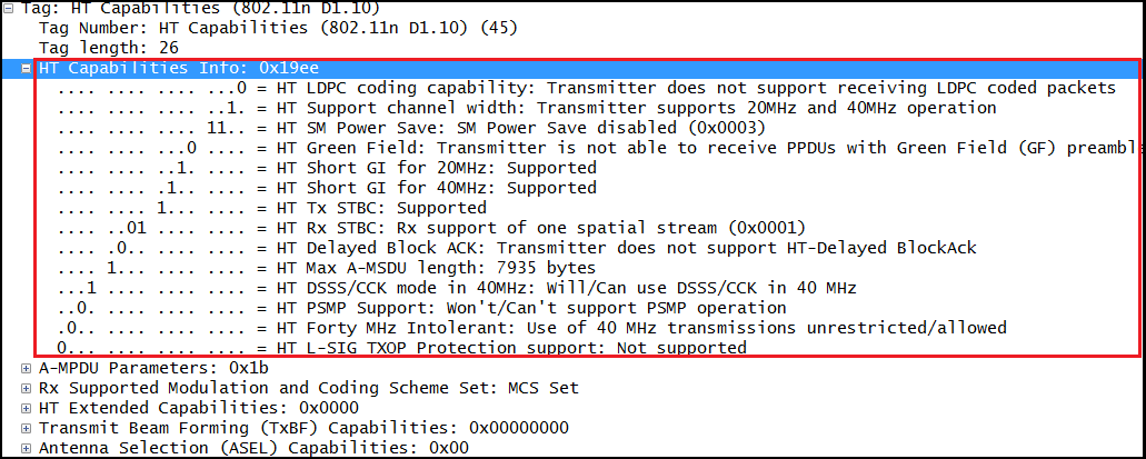 LDPC Coding Capability– Indicating Low Density Parity Check usage.
Supported Channel Width– 0 for only 20MHz, 1 for both 20MHz & 40MHz support.
SM Power Save – to indicate STA SM Power Save capability. Here are the possbile values & their interpretation.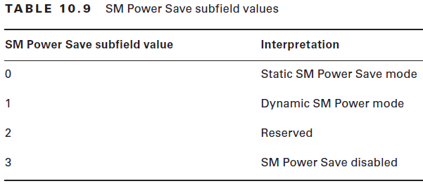 HT Greenfield – When set to 1 STA is capable of receiving HT Greenfield PPDU.
Short GI for 20MHz – STA capability to receive frames with a short GI in 20MHz
Short GI for 40MHz – STA capability to receive frames with a short GI in 40MHz
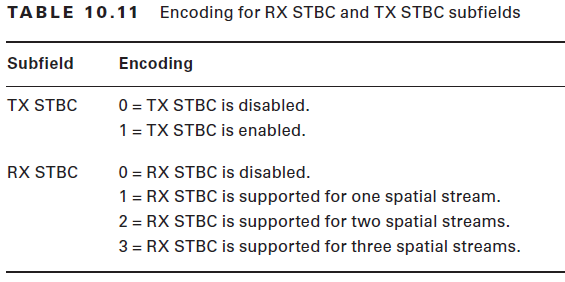
TX STBC – STA capability of transmitting PPDU using STBC (Space Time Block Coding)
RX STBC– STA capability of receiving PPDU using STBC (Space Time Block Coding)
 HT Delayed BlockAck– indicate STA support of Delayed BlockAck
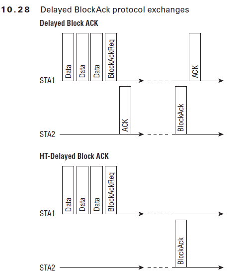 Maximum A-MSDU Length – Aggregate MSDU frame, 0=3839 bytes, 1 =7935 bytes
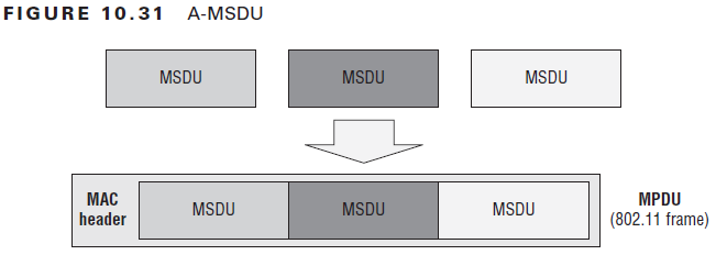
DSSS/CCK Mode in 40MHz –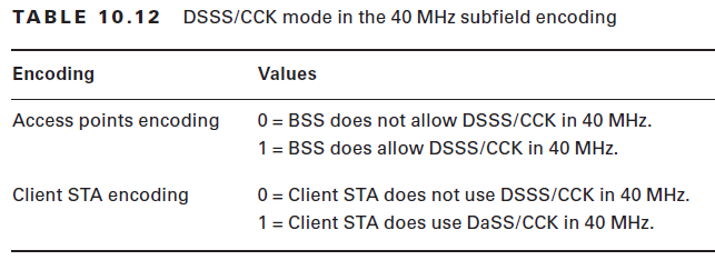 PSMP support –
Forty MHz Intolerant – 1=prohibit use fo 40MHz channel in 2.4GHz
L-SIG TXOP – 1 to indicate support for Legacy-Signal (L-SIG) protection mechan
4. A-MPDU Parameters (1 byte)
Below diagram shows the format of A-MPDU parameter field of the HT Capabilities IE.
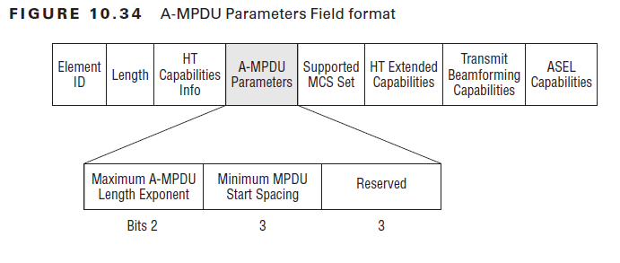 Maximum A-MPDU Length Exponent
Used by STA during association to define maximum A-MPDU length that the STA can receive. The value of this sub-field is an interger between 0-3 from which length in bytes calculated using below formula.
2^(13 + Maximum A-MPDU Length Exponent) – 1
So if value 0=8191 (8K), 1=16383 (16K), 2=32767 (32K) & 3=65535 (64K)
 Minimum MPDU Start Spacing
Specifies the minimum amount of time that must elapse between starting the transmission of one MPDU & starting to transmit the next one. Following values shows the encoding for this sub-field.(in the above capture it show value of 6 indicate 8 microseconds)
0 = no restriction
1 = 1/4 μs
2 = 1/2 μs
3 = 1 μs
4 = 2 μs
5 = 4 μs
6 = 8 μs
7 = 16 μs
3rd sub-field of A-MPDU parameter is reserved.
5. Supported MCS set (16 bytes)
Below figure shows the frame format of the “Supported MCS Set” sub-field.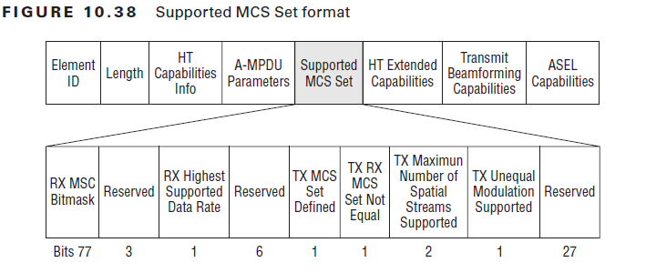 Here is a frame capture shows these sub-fields
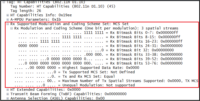 RX MCS Bitmask– has one bit for each 77 (0-76) MCSs. Above shows it support MCS0-23.
RX Highest Supported Rate – Define the highest data rate that STA support, however a STA is not required to provide that infor & may set to 0.TX Supported MCS set –
TX & RX MCS set –
TX Max Spatial Stream Supported –
TX Unequal Modulation –
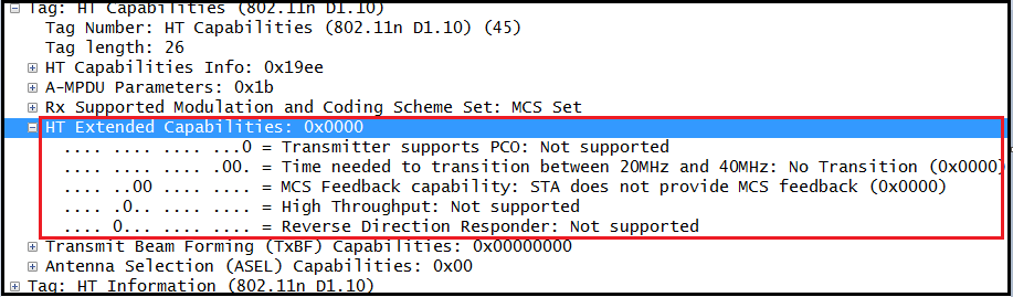
 6. HT Extended Capabilities (2 bytes)
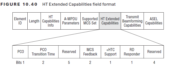 Here is a frame capture.
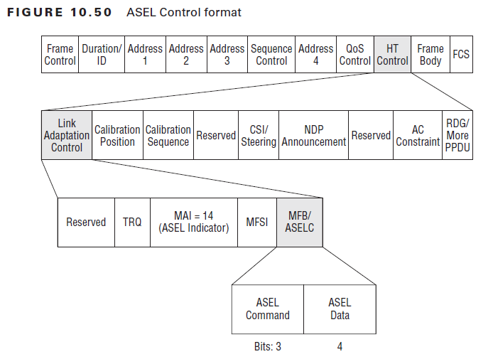
 7. Tx Beamforming Capabilities-TxBF (4 bytes)
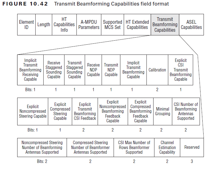 Here is the frame capture shows these sub-fields.
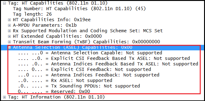
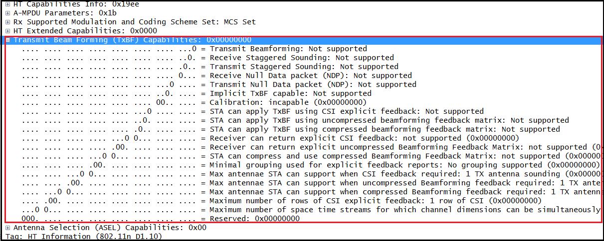 8. ASEL Capabilities (1 byte)
 Here is those filed in the captured beacon.
 Reference
1. CWAP Official Study Guide – Chapter 10
Related Post
1. CWAP – Introduction to 802.11n
2. CWAP – HT Control Field
3. CWAP – HT Operations Information Element

Hello,
Regarding the size of an aggregate frame type A-MPDU, as written in “802.11n – A Survival Guide” (M. Gast, 2012), the size of an A-MPDU frame is only limited by the 802.11n PLCP. It is also noted that the allowed values for A-MPDU are: 8, 16, 32, and 64 kB.
My question is: Is the size of an A-MPDU is fixed in practical (in real devices), or it can vary depending on the total size of IP packets? If it varies, is there any threshold to construct the A-MPDU with different option (8kB, 16kB, etc.)?