
Tags
802.11be, eMLSR, IntelBE200, MLO, WiFi7
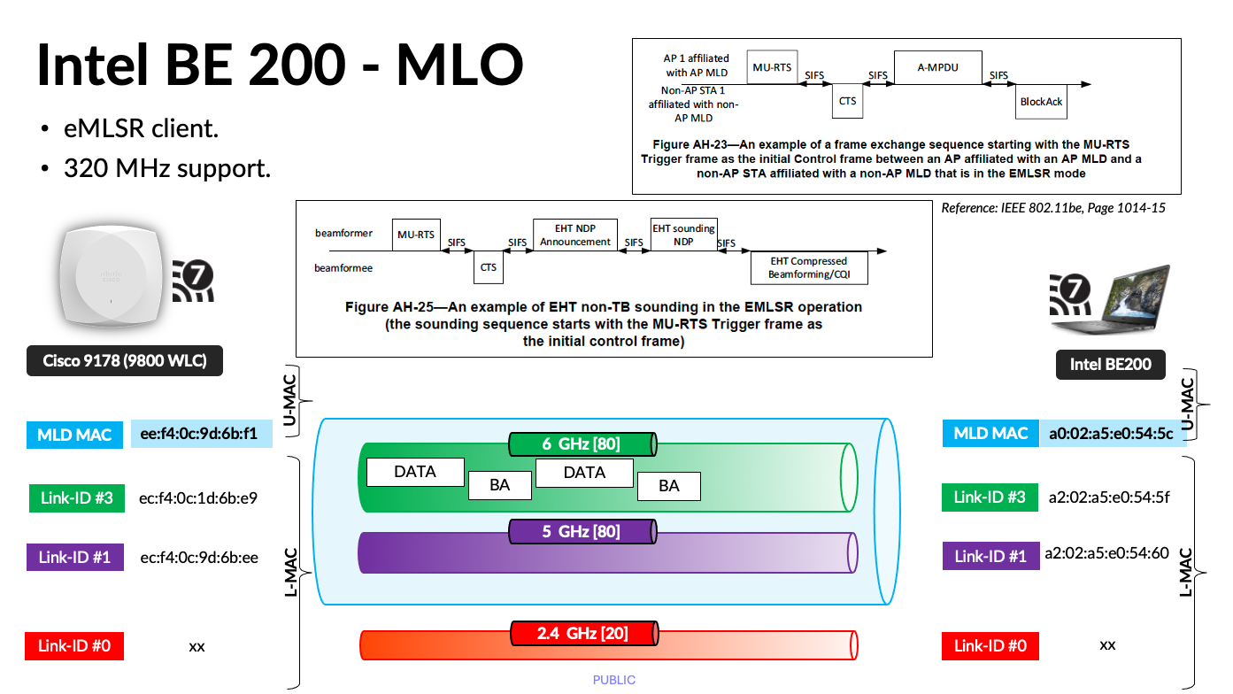
Using the Intel BE200 adapter, I set out to put Enhanced Multi‑Link Single Radio (eMLSR) to the test and examine whether it truly delivers on its promise of seamless link switching. By introducing controlled interference and analysing the traffic at the packet level with Wireshark, we can move beyond marketing claims and observe how Initial Control Frames (ICFs) actually behave in a real‑world 6 GHz environment. Is the handover really as “hitless” as advertised, or are there hidden latency and performance trade‑offs? Let’s inspect the frames and find out.
In eMLSR mode, a Multi‑Link Device (MLD) can monitor multiple frequency bands using a single radio. For example, an Intel BE200 client with a 2×2 radio can logically split that radio into two 1×1 links, allowing it to listen on both 5 GHz and 6 GHz bands.
When traffic needs to move from one band to another, the AP initiates the transition by transmitting an Initial Control Frame (ICF), which is carried as an MU‑RTS on the target band. If the client acknowledges this request with a CTS response, the data transmission switches to the new band in a controlled and near‑seamless manner.
The IEEE 802.11be amendment defines this frame exchange and timing in detail, including the eMLSR frame flow illustrated in Figures AH‑23 and AH‑25.
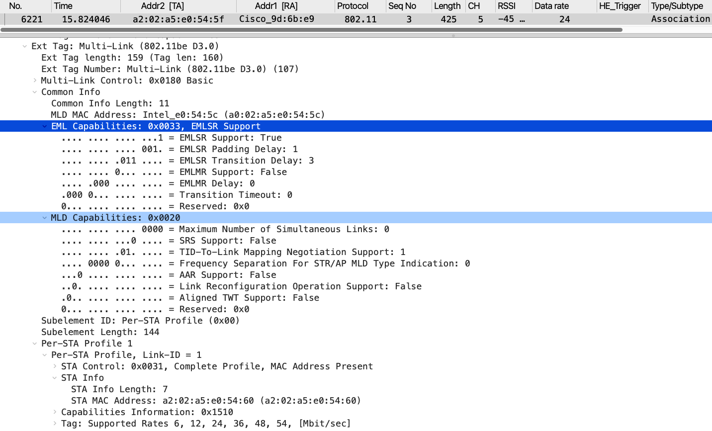
Here is the link to both PCAP files captured during this lab testing. In the .pcap file, if you apply the filter Wi‑Fi 7 → ML Association → MLSR, you will find the Intel BE200 Association Request frame (frame #6221). This frame includes both the MLD Capabilities and EML Capabilities fields within the Multi‑Link element.
The value “Maximum Number of Simultaneous Links = 0” indicates that this is a single‑radio device, meaning traffic can be transmitted simultaneously over one link. (Per the standard, this value is offset by one, so you must add +1 to obtain the actual number of supported simultaneous links.)
The presence of the EML Capabilities field confirms that this device is eMLSR‑capable.
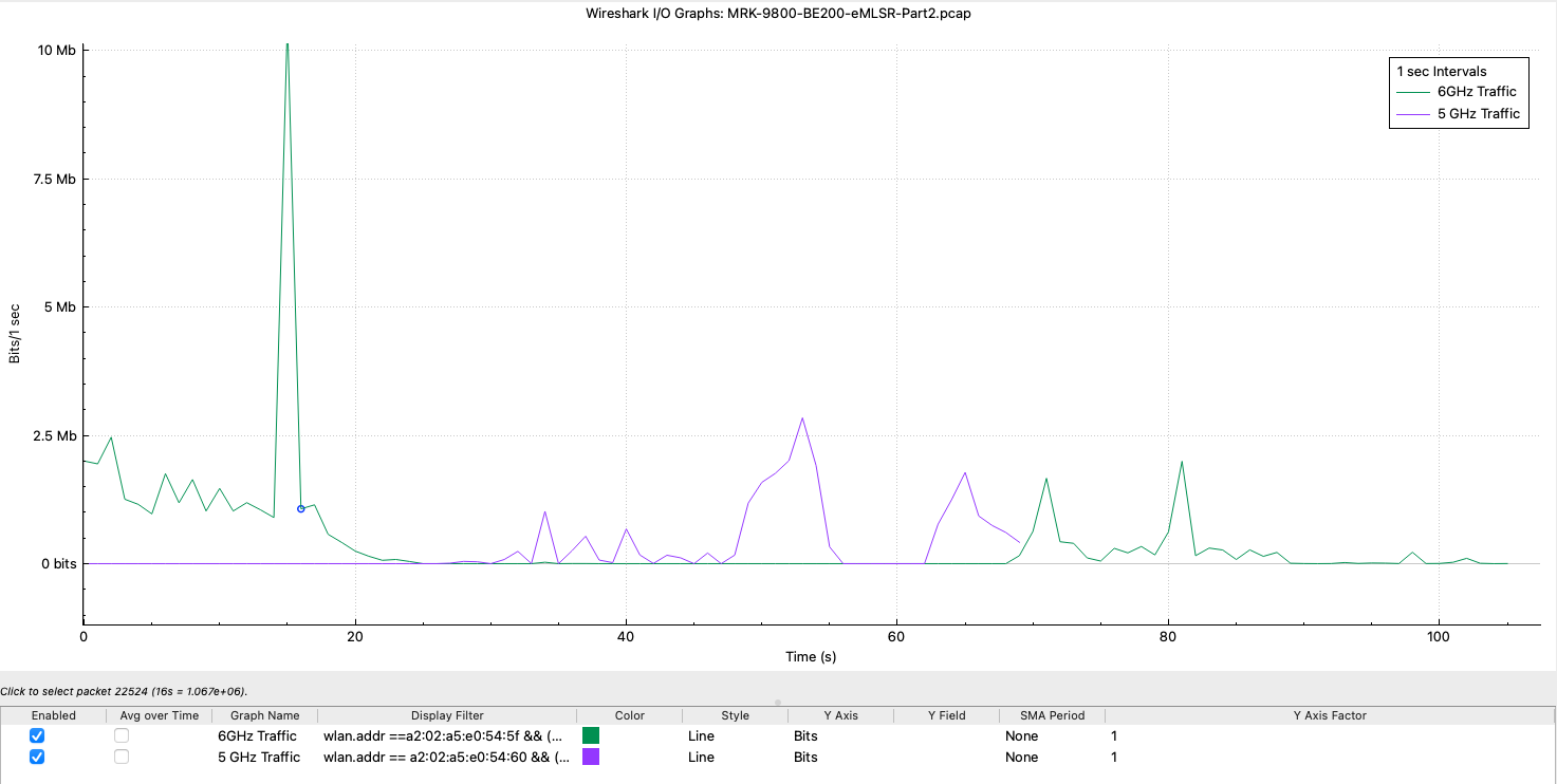
Here are the two PCAPs took during this testing. If you look at ‘MRK-9800-BE200-eMLSR-Part2.pcap’ you can find traffic transition from 6GHz to 5GHz.
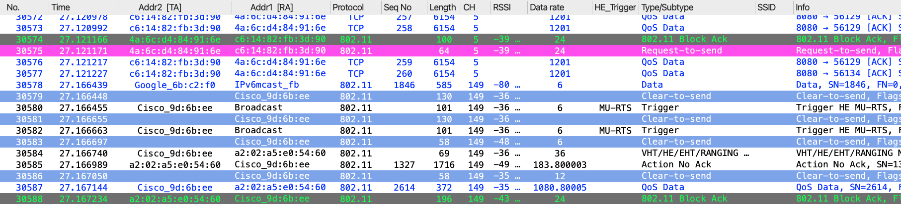
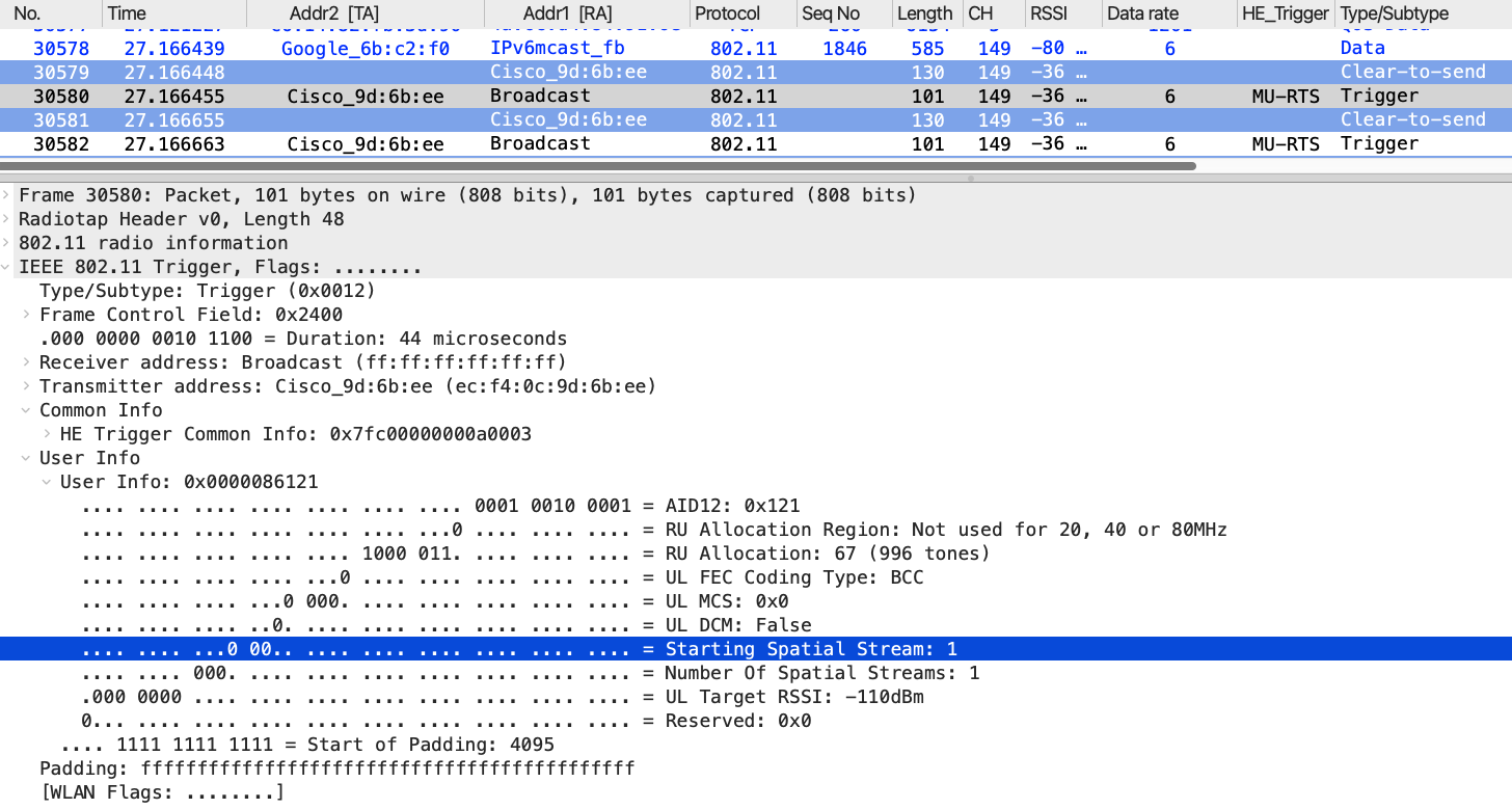
The MU‑RTS frame (#30580) is transmitted over 5 GHz using a 1×1 spatial stream, even though the previous data was sent over the 6 GHz link. The receiver address is Broadcast, with my client’s AID included.
You can filter traffic for the Intel BE200 5 GHz (a2:02:a5:e0:54:60) and 6 GHz (a2:02:a5:e0:54:5f) link‑specific addresses. This allows you to clearly identify the eMLSR behavior, where traffic is sent over only one link at a time. When load was introduced on the 6 GHz link, traffic switched to 5 GHz at around the ~25 s mark. It then switched back to 6 GHz at around the ~70 s mark.
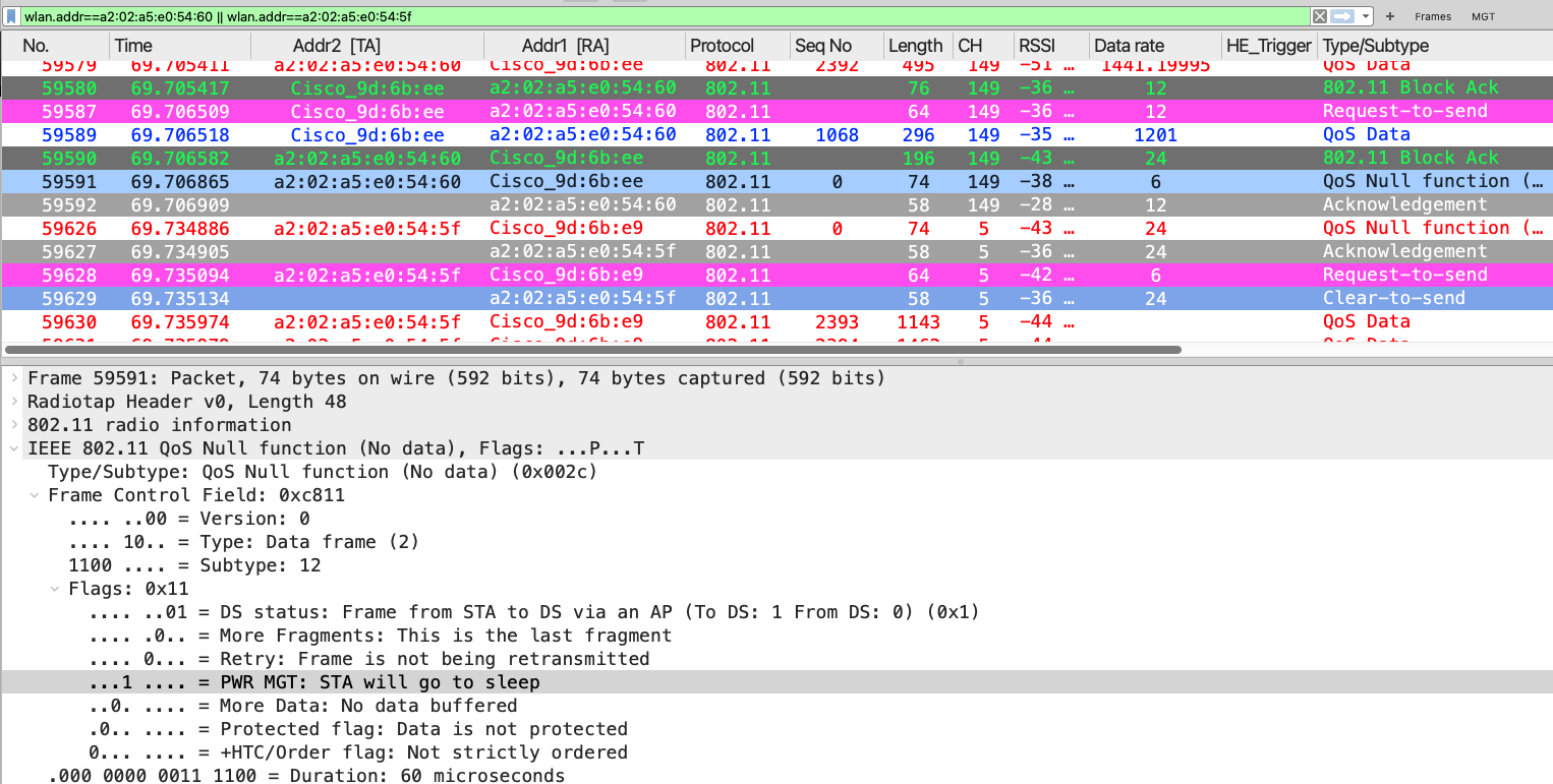
When traffic switches back to the 6 GHz link at around ~70 s mark, you can see that the client initiates this by simply sending a null data frame with PS=1 (#59591) on the 5GHz link. It then immediately brings up the 6 GHz link by sending a QoS null frame on that link with PS=0 (#59626), effectively indicating to the AP that it is now active on that link.
I hope this post gives you a good idea of how eMLSR is in action. This is the most common type of Wi-F7 clients that I have seen in the real world.
