
Let’s see how we can configure a switchport connected to VoIP phone. Here is my setup for this post.

Here is the SPAN configuration.
monitor session 1 source interface Fa1/0/7
monitor session 1 destination interface Fa1/0/9 encapsulation replicate
!
interface FastEthernet1/0/9
 description BACKTRACK
First we will configure as a simple access vlan & see what’s happen.
interface FastEthernet1/0/7
 description VOIP PHONE
 switchport mode access
 switchport access vlan 130
 spanning-tree portfast
If you look at a packet capture in this scenario, you would see a CDP packets send by both Phone & Switch.
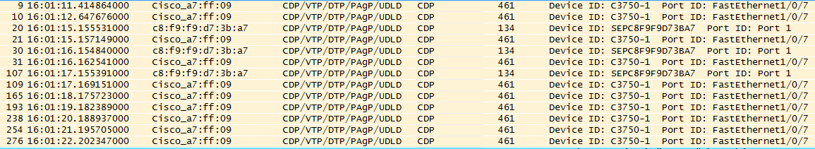
Here is the CDP information send by Switch.
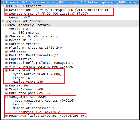
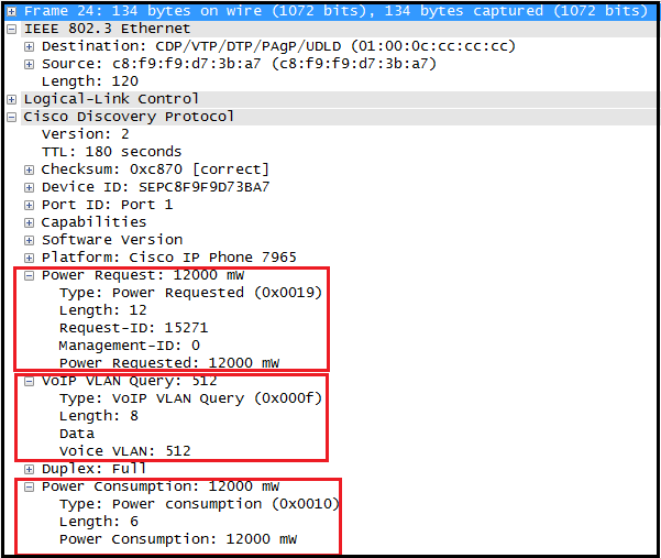
Here is the information send by phone via CDP. As you can see phone will inform power requirement via CDP. Therefore it is very important to have CDP enable on these switch port where you connect VoIP phones (this applies to any cisco PoE devices like AP, Camera, etc)

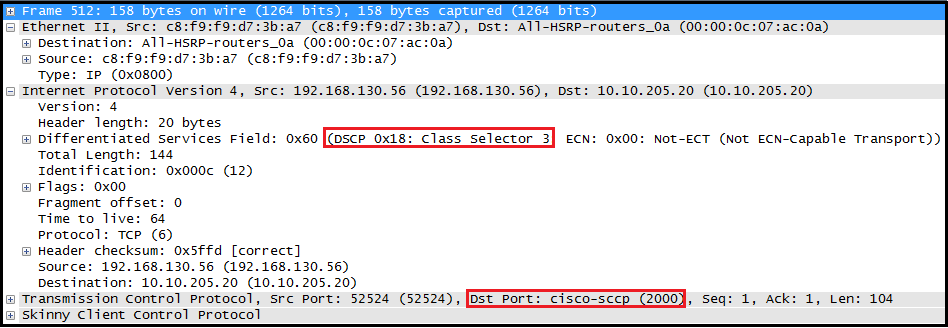
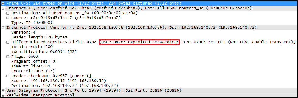
Then Phone & PC get IP via DHCP on vlan 130 & start normal communication. Here is SCCP & RTP packets coming from 7965 phone in this scenario. Since switchport is access port no vlan-tag is coming in those frames.
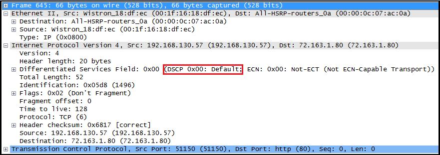
Here is a packet coming from PC.
In the above method both Phone & PC would be on the same vlan. In best practice scenario you would like to put phones & PC in two different vlan. By using “switchport voice vlan x” command you can do this. In that scenario switchport is carry two different VLAN traffic even though we have not configured it as a trunk port.
interface FastEthernet1/0/7
 description VOIP PHONE
 switchport mode access
 switchport access vlan 140
 switchport voice vlan 130
 spanning-tree portfas
As you can see below, switch will inform voice vlan information to the phone via CDP. Also note that this time layer 2 vlan tagging is available in these frames

Here is a CDP packet coming from Phone is same as previous time.
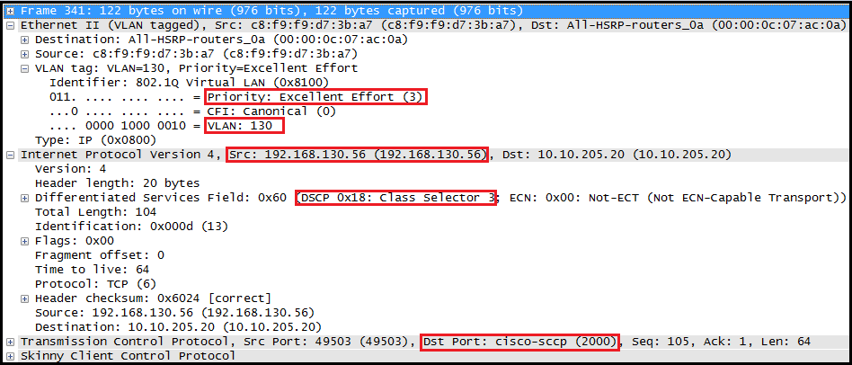
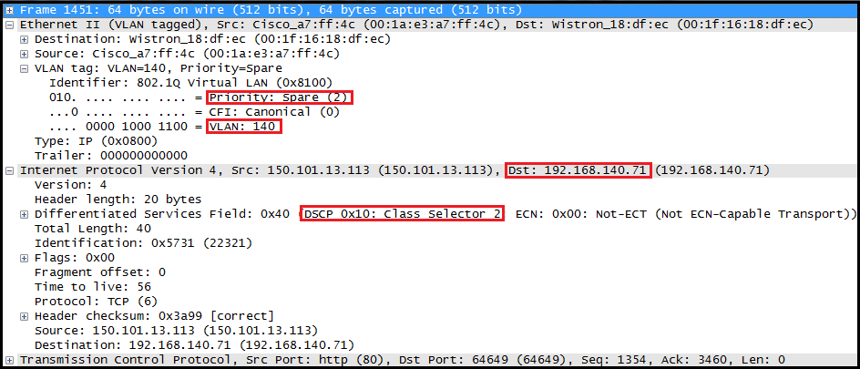
Here is the SCCP packet coming from Phone this time. Note that it comes with layer2 vlan tag which include priority.
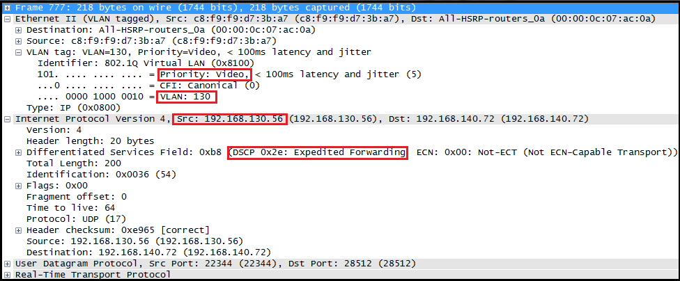
Here is the RTP traffic coming from the phone. You can see phone will set CoS value 5 for this RTP traffic in layer 2 header.
All traffic coming from PC will be on vlan 140 will be un-tagged (as Phone will only tagged it’s own traffic with layer 2 vlan)

But you can see from switch to Phone still traffic will be tagged on vlan 140.
From QoS perspective you wanted to trust priority set by phone for voice traffic. For PC traffic is “untrusted” in normal scenario you do not want to trust DSCP value of those packets. So best option is to trust CoS at the switchport. You can do this trust relationship conditionally in order to end device directly connect to switchport & sending frame with layer 2 tag. So in this example as long as siwtch detect a Cisco-Phone via CDP it will trust CoS value set by that phone.
C3750-1(config)#int fa1/0/7
C3750-1(config-if)#mls qos trust cos

C3750-1(config-if)#mls qos trust device ?
  cisco-phone  Cisco IP Phone
  cts          Cisco-telepresence
  ip-camera    Cisco video surveillance camera
C3750-1(config-if)#mls qos trust device cisco-phone
If you want to prioritize voice traffic (EF) over any other traffic, you have to enable priority-queue in 3750/3560/2960 switch platforms as it is not ON by default.
C3750-1(config-if)#priority-queue ?
  out  egress priority queue
C3750-1(config-if)#priority-queue out
So final switchport configuration is looks like this.
interface FastEthernet1/0/7
 description VOIP PHONE
 switchport mode access
 switchport access vlan 140
 switchport voice vlan 130
 priority-queue out
 mls qos trust device cisco-phone
 mls qos trust cos
 spanning-tree portfast
You can verify switch port configured features by using “show interface x switchport” command.
C3750-1#sh interfaces fa1/0/7 switchport
Name: Fa1/0/7
Switchport: Enabled
Administrative Mode: static access
Operational Mode: static access
Administrative Trunking Encapsulation: negotiate
Operational Trunking Encapsulation: native
Negotiation of Trunking: Off
Access Mode VLAN: 140 (MyHome)
Trunking Native Mode VLAN: 1 (default)
Administrative Native VLAN tagging: enabled
Voice VLAN: 130 (Voice)
Administrative private-vlan host-association: none
Administrative private-vlan mapping: none
Administrative private-vlan trunk native VLAN: none
Administrative private-vlan trunk Native VLAN tagging: enabled
Administrative private-vlan trunk encapsulation: dot1q
Administrative private-vlan trunk normal VLANs: none
Administrative private-vlan trunk associations: none
Administrative private-vlan trunk mappings: none
Operational private-vlan: none
Trunking VLANs Enabled: ALL
Pruning VLANs Enabled: 2-1001
Capture Mode Disabled
Capture VLANs Allowed: ALL
Protected: false
Unknown unicast blocked: disabled
Unknown multicast blocked: disabled
Appliance trust: none
Hope this is useful to understand switch port configuration to be done when it comes to VoIP phone connection.
Here is few reference talk about this voice vlan configuration.
1. Good Explanation of Voice Vlan
2. Switchport Voice Vlan – What does it do ?
Related Posts
1. 3750/3560/2960 Wired QoS
2. Who do you trust ? (DSCP or CoS)
3. QoS for H-REAP
4. Best Practice QoS Config
5.
switchport mode access

Reblogged this on ytd2525.
Given the setup at the beginning of this great post, I still can’t understand how do you capture those packets with 8021.q tags. Switch strips off the vlan tag before it is delivered to PC.
Hi Alex,
Once you configure the voice vlan on a switchport, then phone will tag the packet & pass it to the switchport. In my case I have captured traffic of fa1/0/7 where VoIP phone is connected, not a PC connected port. So packets comes with 802.1q
HTH
Rasika
what a brilliant explanation is this!
this post is what i have been looking for! thanks a lot
Thank you Kim, Yes I know it is long overdue response from my end.
KIT
Rasika
Hello Nayarasi,
could you explain how can tagged traffic (voice vlan 130) pass through the interface fa 1/0/7? I thought tagged traffic from access port can’t will be discarded.
Thanks.
correction 🙂
I thought tagged traffic from access port will be always discarded.
Hi Pavol,
It is not standard access port. Cisco called it “multi-vlan access port”, you can think of a trunk port behavior (not 100% though)
HTH
Rasika
Hi Rasika,
See below excerpt from what you have shared above:
“But you can see from switch to Phone still traffic will be tagged on vlan 140”
First off, VLAN 140 is an access VLAN so traffic will be untagged meaning no dot1q header for packets that are in between PC and Switch..correct me if I am wrong. Secondly, you said that Switch to Phone traffic will be tagged on VLAN 140. How is this possible? Isn’t the VLAN 140 an Access VLAN and the packets are destined towards the PC and they are not going be tagged on VLAN 140 but untagged.
Please help!
Hi Nick,
Note that even we configured it as access port, it is not standard access port. Cisco called it multi-vlan access port.
Those two reference links given in the original post got more details. Pls have a look.
Regarding data vlan tagging from switch to PC only, I am not sure PC to switch tagging was not there due to limitation of that NIC. I have to check it again. Will let you know if I find something different.
HTH
Rasika