
DCF– Distributed Coordination Function : Non-QoS WLAN
HCF with EDCA – Hybrid Coordination Function : QoS WLAN
EDCA– Enhanced Distributed Channel Access
PCF – Point Coordination Function (not implemented practically)
Physical Carrier Sense: Layer 1 – Clear Channel Assessment (CCA)
– ED (Energy Detection)
– CS (Carrier Sense or Preamble detection)
Virtual Carrier Sense : Layer 2 – Network Allocation Vector (NAV) – Duration value set in each frame’s MAC header where other stations set their NAV to this if the sense medium is busy.
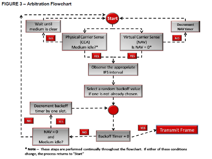
These are the steps a station go through prior to transmit a frame to the wireless medium
1. STAs use a physical carrier sense (Clear Channel Assessment—CCA) to determine if the wireless medium is busy.
2. STAs use virtual carrier sense (Network Allocation Vector—NAV) to detect if the medium is busy. When the virtual timer (NAV) reaches zero, STAs may proceed.
3. If conditions 1 and 2 are met, STAs wait the necessary IFS interval, as prescribed by the protocol.
4. If conditions 1 and 2 are met through the duration of condition 3, STAs generate a random backoff number in accordance with the range of allowed values.
5. STAs begin decrementing the backoff timer by one for every slot time duration that the wireless medium is idle.
6. After decrementing the backoff value to zero, with an idle medium, a STA may transmit the allotted frame exchange, in accordance with the parameters of the obtained transmission opportunity (TXOP).
7. If another STA transmits before Step 6 is completed, STAs observe steps 1, 2, 3, and 5 until the backoff timer is equal to zero.
8. After a successful transmission, repeat as needed. Below diagram show the flow of the above steps (source : 802.11 Arbitration CWNP white paper)
 Inter Frame Spaces
After each frame transmission 802.11 protocol require an idle period on the medium called Inter Frame Space (IFS). The length of the IFS is depend on previous frame type, following frame type, access category, coordination function in use & PHY type as well. The purpose of an IFS is both to provide a buffer between frames to avoid interference as well as to add control and to prioritize frame transmissions.
SIFS (Shortest Inter Frame Space)
SIFS are used within all of the different coordination functions. For 802.11-2007, SIFS is the shortest of the IFSs and is used prior to ACK and CTS frames as well as the second or subsequent MPDUs of a fragment burst. However, with 802.11n, a shorter IFS (RIFS) was introduced.
SIFS for 802.11b/g/n (2.4 GHz) = 10μS
SIFS for 802.11a/n/ac (5 GHz) = 16μS
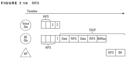
RIFS (Reduced Inter Frame Space)
RIFS were introduced with 802.11n to improve efficiency for transmissions to the same receiver in which a SIFS-separated response is not required, such as a transmission burst (CFB-Contention Free Burst)
RIFS = 2μS
802.11n standard use RIFS & Block Acknowledgement (mandatory in 802.11n). RIFS is used only when Block ACK is enabled. When Block ACK are used, data frames of a CFB may send consecutively without interruption by ACK. At the end of CFB, Tx Station will simply send BAR (BlockACKRequest) & receiving a single Block Acknowledgement (BA).
Below shows the use of RIFS during a 802.11n frame transmission. (page 260 CWAP study guide). Note that AIFS used initially as of QoS Data frames.
 DIFS (Distributed Inter Frame Space)
When a STA desires to transmit a data frame (MPDU) or management frame (MMPDU) for the first time within a DCF network, the duration of a DIFS must be observed after the previous frame’s completion. The duration of a DIFS is longer than both the SIFS and PIFS.
DIFS = SIFS + 2x SlotTime
SlotTime for 802.11a/n/ac (5 GHz) = 9μS
SlotTime for 802.11g/n (2.4 GHz – HT or ERP) = 9μS with short preamble
SlotTime for 802.11g/n (2.4 GHz – HT or ERP) = 20μS with long preamble
SlotTime for 802.11b/g/n (2.4 GHz – DSS ) = 20μS
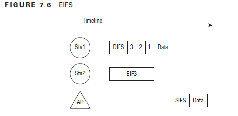
EIFS (Extended Inter Frame Space)
The EIFS value is used by STAs that have received a frame that contained errors. By using this longer IFS, the transmitting station will have enough time to recognize that the frame was not received properly before the receiving station commences transmission. If, during the EIFS duration, the STA receives a frame correctly (regardless of intended recipient), it will resume using DIFS or AIFS, as appropriate
EIFS (in DCF) = SIFS + DIFS + ACK_Tx_Time
EIFS 802.11b/g/n devices using DSS = 364μS
EIFS 802.11g/n devices using OFDM = 160μS
EIFS 802.11a/n devices (5GHz) = 160μS
EIFS (in EDCA) = SIFS + AIFS[AC] + ACK_Tx_Time
Below diagram show the arbitration process after receipt of a corrupted frame, where all other stations (except the transmitter) wait for EIFS.
 Near/Far Problem: Due to side effect of EIFS, stations near to AP could cause problem to stations at Far(hence called Near/Far problem). When data send between AP & near by stations, they can use high data rates where far stations cannot be demodulate & interpret as corrupted frame. So far stations stay quiet for EIFS, while the near station will be allowed to use DIFS or AIFS. The use of DIFS will give nearby station higher priority & get more opportunity to transmit while far station remain quiet.
PIFS (PCF Inter Frame Spaces)
PIFS are used by STAs during the contention-free period (CFP) in PCF mode. Because PCF has not been implemented in 802.11 devices, you will not see PIFS used for this purpose. In order to gain priority over other STAs during contention, the AP can transmit a Channel Switch Announcement (802.11h) frame after observing a PIFS
PIFS = SIFS + SlotTime
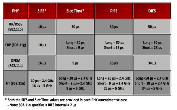
Below chart summarize SIFS,DIFS,PIFS & SlotTime values described earlier.
 AIFS (Arbitration Inter Frame Space)
The AIFS shall be used by QoS STAs to transmit all data frames (MPDUs), all management frames (MMPDUs), and the following control frames: PS-Poll, RTS, CTS (when not transmitted as a response to the RTS), BlockAckReq, and BlockAck (when not transmitted as a response to the BlockAckReq).
The number of slot times used in the AIFS is called the Arbitration Inter Frame Space Number (AIFSN). 802.11e specifies 4 access categories (AV_VO : Voice, AC_VI : Video, AC_BE : Best Effort & AC_BK : Background). Voice & Video category use 2 slottimes by default. Best Effort category use 3 slottimes where as Background traffic use 7 slottimes by default.
Below is the formula to calcluate AIFS for a given Access Category (AC)
AIFS[AC] = AIFSN[AC] × SlotTime + SIFSTime
Contention Window/Backoff Timer
After a STA has observed an idle wireless medium with carrier sense (CS) for the appropriate IFS interval (DIFS, EIFS, or AIFS). To contend for medium access after the IFS, each station selects a backoff value called random backoff period and is selected at random by the STA from a window of possible values called a contention window (CW) calculated using the below formula where x is a value increments with each failed frame.
CW = 2^x -1
For DSS based networks x starts at 5 which resulting CW of 31, for OFDM based networks, x starts at 4 which result in a CW of 15. In both DSS & OFDM x values stops incrementing at 10 which result CW of 1023. Below table summarize these values for DCF network.
 In EDCA medium access (QoS stations & AP), each AC has a CW_min & CW_max. These default values are derived from the following formula.
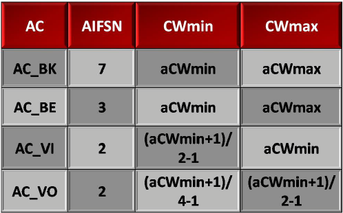 For example, in OFDM aCWmin is 15. This result CWmin for AC_VO =3 {[(15+1)/4] – 1} & CWmax for AC_VO=7 {[(15+1)/2]-1}. In the same way CWmin for AC_VI=7 {[(15+1)/2] -1} & CWmax for AC_VI=15. For AC_BE & AC_BK those values are 15 & 1023 respectively.
For an initial attempt at a frame transmission, the CW is the aCWmin value.For each attempted retransmission, the CW is increased exponentially until the CW reaches the aCWmax. In this case, the CW remains at the aCWmax until a successful frame sequence is performed or the number of attempted retransmissions reaches the max retry count. Below diagram shows this concept
 TXOP- Transmit Opportunity
EDCA introduce this TXOP which is a time period where one device, called TXOP holder has unfettered acccess to the channel for data transmission. The data frame transmissions within a TXOP are called a “contention free burst -CFB” During a TXOP, only the data that makes up a CFB and the ACK for that data may access the channel.
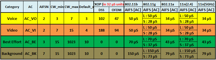
802.11e standard defines default TXOP limit value for each AC, but values can be configured on AP. TXOP limit are set in intervals of 32µs (microseconds). Default TXOP is 47 for AC_VO (47×32=1504µs) for OFDM. It is 94 for AC_VI (94×32=3008µs) . Note that for AC_BE & AC_BK always TXOP set to 0, in other words those traffic category always has to send one frame at at time (no CFB).
Here is the default settings (AIFSN, CW_min, CW_max, x value, TXOP, AIFS) of those four access categories.
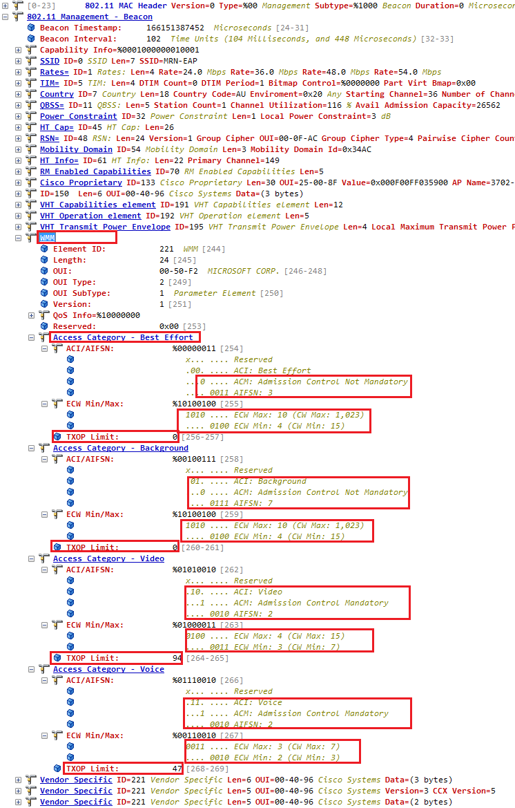
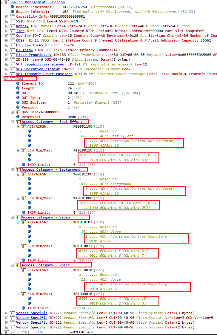
 Here is a beacon frame of a 802.11a radio where you can see those default settings as well.
 As explained these EDCA value can be configurable on AP. Here is on my Cisco WLC (3850) I have changed the default setting to optimized Voice & Video. “wmm-default” is the default setting in this WLC.
3850-1(config)#ap dot11 5ghz shutdown
3850-1(config)#ap dot11 5ghz edca-parameters ?
  custom-voice           Enable Custom Voice parameters for 802.11a
  optimized-video-voice  Enable combined video-voice-optimized parameters for 802.11a
  optimized-voice        Enable non-spectralink voice-optimized parameters for 802.11a
  svp-voice              Enable SpectraLink Voice Priority (SVP) parameters for 802.11a
  wmm-default            Enable WMM default parameters for 802.11a
3850-1(config)#ap dot11 5ghz edca-parameters optimized-video-voice
3850-1(config)#no ap dot11 5ghz shutdown

3850-1#show ap dot11 5ghz network | in EDCA
EDCA profile type check : optimized-video-voice
Once you change this, you can see AP advertising these values on WMM parameters & you can see values change to give priority for Voice & Video.
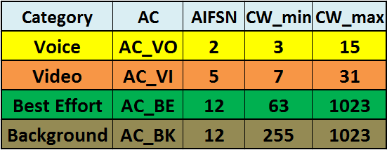 Here is a beacon frame capture showing those modified values.
 Reference
1. CWAP Official Study Guide – Chapter 7
2. 802.11 Arbitration – CWNP White Paper
3. 802.11-QoS-Overview

How to understand DIFS, PIFS and SIFS work with good example?
Here is another good document explain this. See if that helps
Click to access avb-phkl-802-11-qos-overview-0811-1.pdf
Rasika
Great Post and blog. Will definitely follow the blog.
Thanks Pavan.
Great post, this accompanied with some CWDP practice questions is helping me wrap my head around 802.11 contention. One thing that is not clear to me is why AIFS is longer than DIFS? I understand that EDCA is an extension of DCF, however I don’t understand how they interoperate within a single BSS. By enabling EDCA are you directing clients that DIFS (DCF) is no longer used and only AIFS (EDCA) interframe spacing is being observered? If that is true, are non 802.11e compliant devices unable to join the BSS when EDCA is enabled? I guess I don’t understand how (and if) DCF clients interoperate with EDCA clients when DIFS is shorter than AIFS. Thanks! Mike
Hi,
Thank you for and educational article.
I have a question.
This is a Maximum throughput calculation for 802.11a:
MTa (8k * Ldata)/(kTdata+Tack+Tdifs+Tsifs+(CWmin-1)Tslot/2).
Would you be able to tell me what is the maximum throughput formula for 802.11n please?
Thank you.
Regards,
Vladimir
This is great been going crazy trying to understand this in depth. In short we basically have:
1- CCA
2- NAV
3- DIFS
4- CW
5- Tx
NAV portion was confusing me a bit with regards to DCF and was checking this link out:
http://www.cisco.com/c/en/us/td/docs/solutions/Enterprise/Mobility/emob41dg/emob41dg-wrapper/ch5_QoS.html#wp1021972
per this link I do not see any mention of NAV in any of the steps. Did they just miss that step in there?
Thank you
Pingback: My CCNA Wireless Journey | » Ali's Technology Blog
Pingback: Wi-Fi CSMA/CA – Going Deep – ROBROBSTATION
Pingback: Cisco WLC: EDCA timers - NetGab - The daily networking madness
so i did not understand what must be the ifs value for a standart dataframe transmission and which one must be chosen , if a client does not support HT and must use ERP .It seems it must be 10 microsecond but not clear to be sure .
IF client won’t supports it follows SIFS where AP and client supports both HT means uses RIFS.
nayarasi;
you’re just amazing ! thanks for sharing.
Thank you Mohamed, sorry for delayed ACK 🙂
Rasika