
Tags
For wireless network analysis, promiscuous mode is no longer good enough. This mode would require the wireless card to be associated to an access point and would not capture all wireless frames in the environment. By default, many wireless NIC drivers will not pass up 802.11 management and control frames and therefore would not be visible in the protocol analyzer. 802.11 wireless networks are half-duplex, and wireless NICs cannot listen (receive packets) while transmitting.
Because of these issues, wireless analyzers place the NICs into a special mode called RF monitor mode; in this mode, the card becomes a passive monitoring device and cannot transmit, and therefore normal wireless network operation is disabled. In RF monitor mode, wireless NICs listen to all 802.11-encoded signals
on the channel on which they are currently monitoring.
Analyzer Location
Identifying the correct location to place a network analyzer is an essential step in performing successful wireless network analysis. Incorrect placement of the wireless analyzer can lead to false conclusions being made. For example, if you are capturing traffic too far away from the source and destination, you might see a lot of corrupted frames; however, the intended recipient may not be experiencing any frame anomalies.
An access point acts as the central point in an 802.11 wireless network, and all traffic must fl ow through the access point. Therefore, placing the analyzer as close to the AP as possible will allow the wireless analyst to observe the RF environment from the same perspective as the AP.
Capture Options
- Channel Selection & Scanning
- Fixed Channel
Fixed channel analysis will lock the wireless NIC card onto one channel, enabling it to capture all 802.11-encoded traffic on the selected channel. - Channel Scanning
When channel scanning is selected, the wireless NIC will capture traffic on all selected channels, spending a short amount of time on each channel before moving to the next one. - Country code
Within a given frequency band, every country has its own regulations that govern which channels are allowed to be used. After installing a customized analysis driver, you might find that you have the wrong number of channels available within your wireless analyzer. This is likely to be because the driver is configured with an incorrect country code. - 2.4GHz channel overlap
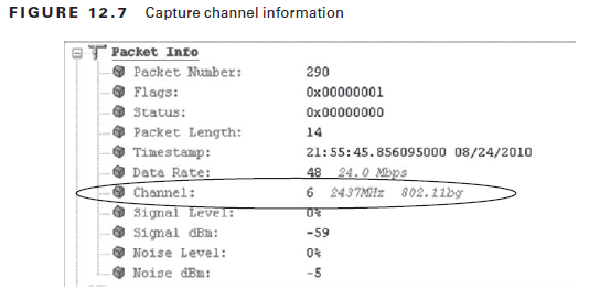
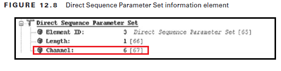
Because the channels in the 2.4 GHz ISM band overlap, it is quite common to capture packets on channels other than the one on which they were originally transmitted. The channel a frame was captured on is displayed in the packet information at the top of every packet decode. To determine the channel a frame was transmitted on, you need to start examining the packet decode. A 2.4 GHz AP advertises the channel the BSS is operating on in the Direct Sequence Parameter Set information element contained in the beacon and probe response frames, as shown below.
 To determine which channel other frame types were transmitted on, because the transmitted channel information is not recorded within the frame. The following three-step procedure can be used to determine the transmit channel of a 2.4 GHz packet:
1. Determine the BSSID from the packet in question. You can find this in the MAC header.
2. Find a beacon frame with a matching BBSID. This could be done using a filter or search.
3. Look up the BSS channel in the Direct Sequence Parameter Set information element.
This method works for all frames transmitted as part of a BSS. However, it is not possible to determine the channel of a probe request frame, because these frames are used for BSS discovery and are transmitted on all channels by stations performing active scanning.
- Fixed Channel
- Buffer size
The capture buffer is an allocation of memory (RAM) that will be reserved for your packet capture. This memory is used by your analyzer to store captured frames. - Save to disk
If you need to capture packets over a sustained period of time, just selecting a large capture buffer will probably not provide enough storage, so the other option is to save the packets to disk. - Packet Slicing
Packet slicing allows you to just capture the first so many bytes of each packet, disregarding the rest of the frame. Often the only information we are interested in is the header information, and we do not have any interest in the data elements of the packets. This is especially the case on wireless networks when encryption is used and the data is unreadable. By using packet slicing, you can store a significantly larger number of packets to disk. - Peer Map Function
A peer map is a visual representation of which STAs are communicating with each other. Lines between peers indicate communication.
Physical peer maps identify which physical devices (identified by their MAC address) are communicating. Physical peer maps draw lines between the source and destination MAC address within the MAC header.
Logical (layer 3) peer maps are also available. On an IP logical peer map, lines are drawn between the source and destination address in the IP header.
Capture Filter vs Display Filters
Capture filters are applied to the packet stream before the packets enter the capture buffer. Anything filtered out at capture time is not stored and therefore cannot be recovered later. Capture filters can make your packet captures more readable by removing unneeded traffic.
Display filters or post-capture filters provide a way of hiding from view unwanted packets.An advantage of display filters is that the packets are only hidden and can be retrieved if required.
Expert Analysis
Expert analysis is the automatic detection of network events, errors, and problems by an analyzer. Expert analysis is a term used by the more traditional protocol analysis vendors, whereas the WIDS vendors tend to refer to their expert analysis as a set of alarms. There are two types of expert analysis, threshold-based and heuristic-based.
- Threshold-Based
Threshold-based expert analysis collects network statistics and compares them to configured threshold values. When the statistics exceed the configured threshold, an expert event is triggered, and a notification is sent. An example of a threshold-based expert event would be “Too many retransmissions,” where the threshold value is configured to trigger this event when retransmissions reach an unacceptable level. - Heuristic-Based
Heuristic-based expert analysis looks for patterns in the traffic flow and compares them to a set of rules. Traffic that does not conform to these rules is reported. A good example of a heuristic-based expert event would be “Inefficient client,” which looks for clients sending data using only small packet sizes.
VoWiFi Analysis
The level of VoWiFi analysis that can be performed if encryption is used on the wireless network will be limited. Although we cannot analyze VoIP calls and their signaling on an encrypted network, we can still analyze two of the most import requirements for voice on a wireless network: QoS and fast efficient roaming.
- WMM Analysis
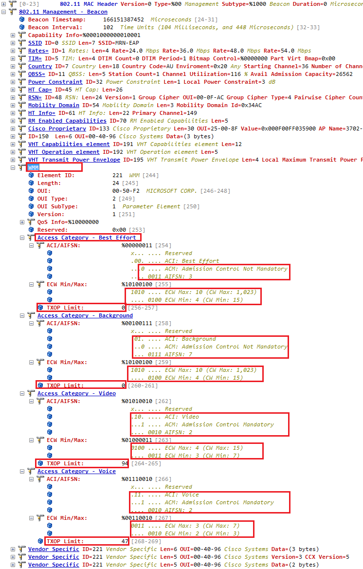
QoS on a wireless network is achieved through the use of wireless multimedia (WMM). WMM-capable access points will advertise their WMM capabilities in beacon frame, as shown below.
- Call Analysis
On unencrypted networks or on networks where you can enter a preshared key to decrypt the packets, you are able to analyze the call and signaling information of your VoIP conversations. Some network analyzers include special VoIP analysis features:- Call list
- Call Quality matrix (MOS & R-Factor)
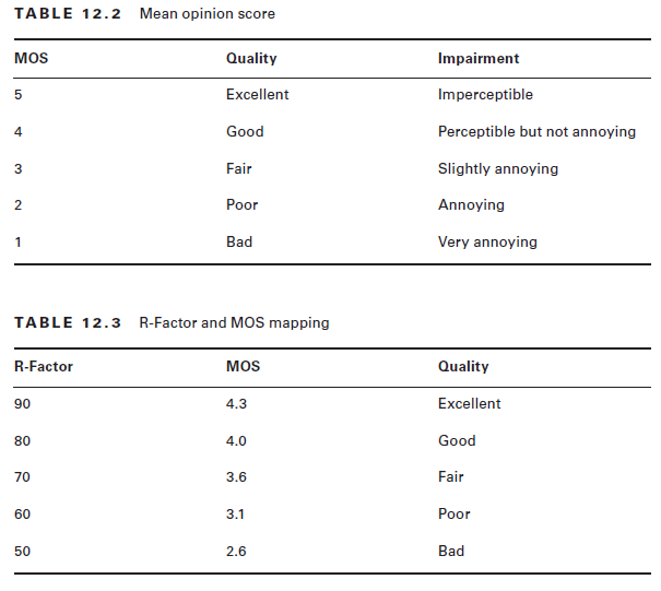
The mean opinion score (MOS) is a value from 1 to 5 that indicates the perceived quality of a call.
MOS score displayed by your protocol analyzer is what is called passive MOS. Passive MOS is calculated from another quality metric that you will see displayed in your protocol analyzer, called R-Factor. R-Factor is calculated from measurable information such as jitter (the variation in packet delay over time), packet loss, and latency. R-Factor is a value from 0 to 100. Below shows the MOS & R-Factor value mapping.
- Signaling diagrams
- Call replay
- VoIP expert events
Multiple Channel Protocol Analysis
One method of capturing traffic on different channels is to configure your wireless analyzer to perform channel scanning. The limitation of channel scanning is that the wireless capture adapter is capable of capturing packets on only one channel at a time and therefore only captures a snapshot of what is happening on each channel analysis or detailed troubleshooting is impossible, because too many of the required packets will be missing.
- Multiple Network Analyzer
In an MCA environment, where the channel sets 1, 6, and 11 have been deployed, this approach would involve three separate analyzers on three separate laptops, with each analyzer configured for a different channel. This would produce three separate packet trace files. - Simultaneous Captures & Multiple Adapter Support
Some analyzers support the ability to start simultaneous captures from different network adapters. The advantage of this approach is that you need only one protocol analyzer; however, you are still left with three separate capture files—one for each channel. - Multichannel Aggregation
Multichannel aggregation takes capture streams from multiple adapters and aggregates them together into one capture. Each adapter can be configured
for a different channel.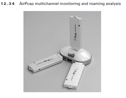

Roaming Analysis
Roaming is the method by which client stations move between RF coverage cells in a seamless manner. Seamless communications for stations moving between the coverage zones within an extended service set (ESS) is vital for uninterrupted mobility.
The best way to troubleshoot a roaming problem is to use an analyzer that supports multichannel aggregation and to confi gure one adapter for each of the channels used by the wireless network.
Distributed Protocol Analysis
- Wireless Analyzer with remote capture probes
- Wireless Analyzer with remote engines
- Centralized server with wireless sensors (WIPS)
References
1. CWAP Official Study Guide – Chapter 12

I want to ask the point that what is the main different in between the wire shake and Promiscuous Mode?
Refer this
http://wiki.wireshark.org/CaptureSetup/WLAN#Promiscuous_mode
HTH
Rasika
Hi Rasika
Which packet analyzer did you use under the “WMM Analysis” section?
Thanks.
http://www.wildpackets.com/products/omnipeek_network_analyzer
Hi Rasika
Just want to know which packet analyzer app did you use under the section “WMM Analysis”?
Thanks.
Hi, I used OmniPeek Network Analyzer
http://www.wildpackets.com/products/omnipeek_network_analyzer
HTH
Rasika
Right. I’ve seen the video about Omnipeek last night and the packet captures looks very comprehensive. Have you tried Metageek’s EyePA before?
Thanks for the reply. 🙂
Pingback: CWAP-403 funtimes – notes #1.1 – #WirelessIsFun