
If “Multicast” is a technology that you scare to work with, you are not alone. Many people confused with this technology and leave it as a difficult technology to understand and configure it in their network.
There are two protocols important in any multicast deployment.
IGMP – Multicast receivers to tell their interest to join to particular group address
PIM – Once IGMP join request received by LHR, PIM protocol forward these messages up to Source of that multicast traffic. Then multicast traffic can flow towards receivers who are interested to receive that traffic.
In IGMP v1(RFC1112) and IGMP v2 (RFC2236), there was no way to receiver can specify a source address of a multicast server, only group address can specify. That require RP-Rendezvous Point in your network to keep records of Multicast Servers, with their Group numbers and facilitate receivers to find those source when they want to join a particular group. Most complexities come due to RP configurations and how network advertise RP existence (eg BSR, AutoRP, Static) to multicast receivers and sources of your network.
With IGMP version 3 (Defined RFC3376 in 2002 & updated RFC4604 in 2006), you can specify Source and Group address in IGMP join, therefore no need of RP on your network. That reduce most of your multicast configuration complexities. In this post we will see how to configure PIM-SSM (source specific multicast) and verify your PIM-SSM multicast configuration.
SSM assumes one-to-many multicast model where single source generate multicast traffic and many receivers interest to receive that traffic. Most of multicast applications fit into that model and hence SSM is the preferred way of implementing multicast on your network today.

In this post we will use only wired connectivity for simplicity and will look at Multicast over wireless (using Cisco 9800 & AP) in a different post. PIM-SSM defined in RFC4607 published in year 2006.
Configuration is very simply, you just enable IP Multicast Routing on all your network devices and make sure IGMP version 3 is enabled on those interfaces. Then enable PIM-SSM specifying which multicast group expect to use SSM (default 232.0.0.0/8). It is that simple and no more complications.
Let’s discuss how you configure it using Cisco IOS CLI commands using given topology.
Let’s configure it on SW2 first. “ip multicast-routing” is the CLI command you required and you may have to used “distributed” keyword in switching platforms.
SW2(config)#ip multicast-routing ?
  distributed  Distributed multicast switching
  vrf          Select VPN Routing/Forwarding instance

SW2(config)#ip multicast-routing distributed
Then you can enable PIM on interfaces that multicast traffic you expect to flow. Switch2 will receive multicast source traffic on vlan 224 and expect to flow through G0/6 interface when receivers requesting multicast traffic from these sources. “pim-sparse” mode is the method that you should configure, as legacy “dense” & “sparse-dense” modes has been deprecated.
On certain switch models, you will see “ip pim sparse-mode” command not supported on SVI interfaces. In my SW2 (Cisco WS-C3560CG-8PC-S), that is the case and hence use “ip pim passive” CLI command to enable PIM on vlan 224. Once you issue that command, it will not send any PIM join messages or accept any PIM join messages from neighbor routers on that interface. Since VLAN224 is being used for Multicast Source, no negative effect by make it PIM passive interface.
SW2(config)#int g0/6
SW2(config-if)#ip pim sparse-mode

SW2(config)#int vlan 224
SW2(config-if)#ip pim ?
passive Enable PIM passive interface operation

SW2(config-if)#ip pim passive
Once you enable PIM on Cisco device, by default that will enable IGMP version 2 on that interface. In IGMP version 2 join request, it will specify only multicast group address (*,G) where source address cannot be specified.
SW2#sh ip igmp interface
Vlan224 is up, line protocol is up
  Internet address is 192.168.224.1/24
  IGMP is enabled on interface
  Current IGMP host version is 2
  Current IGMP router version is 2
  IGMP query interval is 60 seconds
  IGMP configured query interval is 60 seconds
  IGMP querier timeout is 120 seconds
  IGMP configured querier timeout is 120 seconds
  IGMP max query response time is 10 seconds
  Last member query count is 2
  Last member query response interval is 1000 ms
  Inbound IGMP access group is not set
  IGMP activity: 3 joins, 0 leaves
  Multicast routing is enabled on interface
  Multicast TTL threshold is 0
  Multicast designated router (DR) is 192.168.224.1 (this system)
  IGMP querying router is 192.168.224.1 (this system)
  No multicast groups joined by this system
In our case we want to make sure IGMP version 3 enabled. Therefore you can use “ip igmp version 3” CLI command on these 2 interfaces. Here is how you can do it. Note that “ip pim dr-priority 100” command on G0/6 interface is not mandatory, in my case that interface connected to a LAN segment that got other routers other than R1. By configuring higher priority on that switch, we will make it designated router to send PIM join messages for that segment. If priority same, then the highest IP interface router will become PIM DR for that segment.
SW2(config)#int vlan 224
SW2(config-if)#ip igmp ?
  access-group                IGMP group access group
  explicit-tracking           Enable/Disable IGMP explicit-tracking
  helper-address              IGMP helper address
  immediate-leave             Leave groups immediately without sending last
                              member query, use for one host network only
  join-group                  IGMP join multicast group
  last-member-query-count     IGMP last member query count
  last-member-query-interval  IGMP last member query interval
  limit                       IGMP limit
  mroute-proxy                Mroute to IGMP proxy
  proxy-service               Enable IGMP mroute proxy service
  querier-timeout             IGMP previous querier timeout
  query-interval              IGMP host query interval
  query-max-response-time     IGMP max query response value
  static-group                IGMP static multicast group
  tcn                         IGMP TCN configuration
  unidirectional-link         IGMP unidirectional link multicast routing
  v3-query-max-response-time  IGMP v3 max query response value
  v3lite                      Enable/disable IGMPv3 Lite
  version                     IGMP version

SW2(config-if)#ip igmp version ?
  <1-3>  version number

SW2(config-if)#ip igmp version 3


interface GigabitEthernet0/6
 description R1941-G0/0
 no switchport
 ip address 192.168.178.2 255.255.255.0
 ip pim dr-priority 100
 ip pim sparse-mode
 ip igmp version 3
!
interface Vlan224
 ip address 192.168.224.1 255.255.255.0
 ip pim passive
 ip igmp version 3
!
SW2#sh ip igmp interface
GigabitEthernet0/6 is up, line protocol is up
  Internet address is 192.168.178.2/24
  IGMP is enabled on interface
  Current IGMP host version is 3
  Current IGMP router version is 3
  IGMP query interval is 125 seconds
  IGMP configured query interval is 60 seconds
  IGMP querier timeout is 250 seconds
  IGMP configured querier timeout is 120 seconds
  IGMP max query response time is 10 seconds
  Last member query count is 2
  Last member query response interval is 1000 ms
  Inbound IGMP access group is not set
  IGMP activity: 1 joins, 0 leaves
  Multicast routing is enabled on interface
  Multicast TTL threshold is 0
  Multicast designated router (DR) is 192.168.178.2 (this system)
  IGMP querying router is 192.168.178.1
  No multicast groups joined by this system

Vlan224 is up, line protocol is up
  Internet address is 192.168.224.1/24
  IGMP is enabled on interface
  Current IGMP host version is 3
  Current IGMP router version is 3
  IGMP query interval is 60 seconds
  IGMP configured query interval is 60 seconds
  IGMP querier timeout is 120 seconds
  IGMP configured querier timeout is 120 seconds
  IGMP max query response time is 10 seconds
  Last member query count is 2
  Last member query response interval is 1000 ms
  Inbound IGMP access group is not set
  IGMP activity: 4 joins, 1 leaves
  Multicast routing is enabled on interface
  Multicast TTL threshold is 0
  Multicast designated router (DR) is 192.168.224.1 (this system)
  IGMP querying router is 192.168.224.1 (this system)
  No multicast groups joined by this system
On R1, you have to simply apply below configurartions
R1(config)
ip multicast-routing
!
interface GigabitEthernet0/0
 ip pim sparse-mode
 ip igmp version 3
!
interface GigabitEthernet0/1
 ip pim sparse-mode
 ip igmp version 3
You have to do similar configurations on SW1. Note that I got Cisco WS-C3560CX-12PD-S as SW1 and that support “ip pim sparse-mode” command on SVI interfaces too.
SW1#
ip multicast-routing distributed
!
interface GigabitEthernet1/0/14
 ip address 192.168.128.2 255.255.255.0
 ip pim sparse-mode
 ip igmp version 3
!
interface Vlan129
 ip address 192.168.129.1 255.255.255.0
 ip pim sparse-mode
 ip igmp version 3
Now you have enabled PIM with IGMPv3 on all required interfaces you are almost done with configuration. However, you have to specify which multicast group addresses being used. Since IANA allocated 232.0.0.0/8 range allocated for SSM, you can use that with “ip pim ssm default” configuration command. We will used that in our testing.
SW2(config)#ip pim ssm ?
  default  Use 232/8 group range for SSM
  range    ACL for group range to be used for SSM

SW2(config)#ip pim ssm default
!
SW1(config)#ip pim ssm default
!
R1(config)#ip pim ssm default
If you want to change which multicast group use SSM, you can change ip range for SSM, you can do it as shown below. First you define a standard ACL that identify multicast IP range you want to use under SSM. Then you can use “ip pim ssm range <ACL_Name/No>” to map that ACL for SSM range. Examples shown below if you want to use entire multicast range with SSM.
SW2(config)#access-list 25 permit 224.0.0.0 15.255.255.255
!
SW2(config)#ip pim ssm range ?
  <1-99>  Access list number
  WORD    IP named access list

SW2(config)#ip pim ssm range 25
Let’s test our configuration now. You can use VLC player to stream a video as multicast very easily. You can go to “Media –> Stream” and select your video file & click “stream”. I have used a 4K quality video which require ~8Mbps bandwidth in average. It is 642MB file and you can download it from here if you need it for your testing.

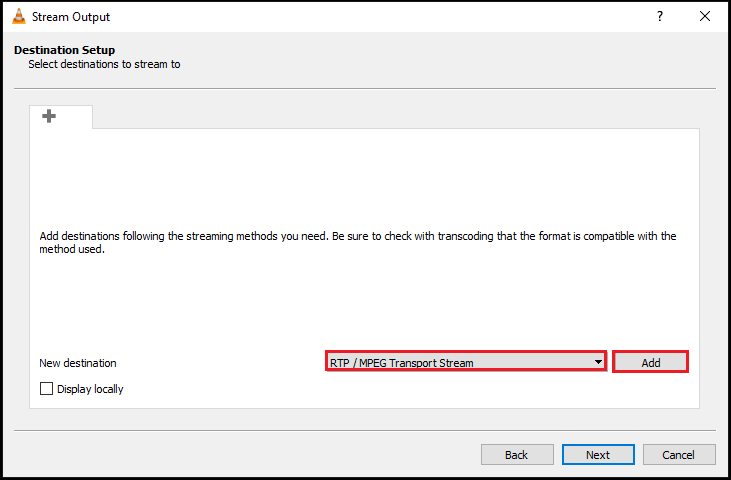
Once you click Stream option, you will get below screen. Simply click “Next” and in the subsequent window select “RTP/MPEG transport system” and click “Add“

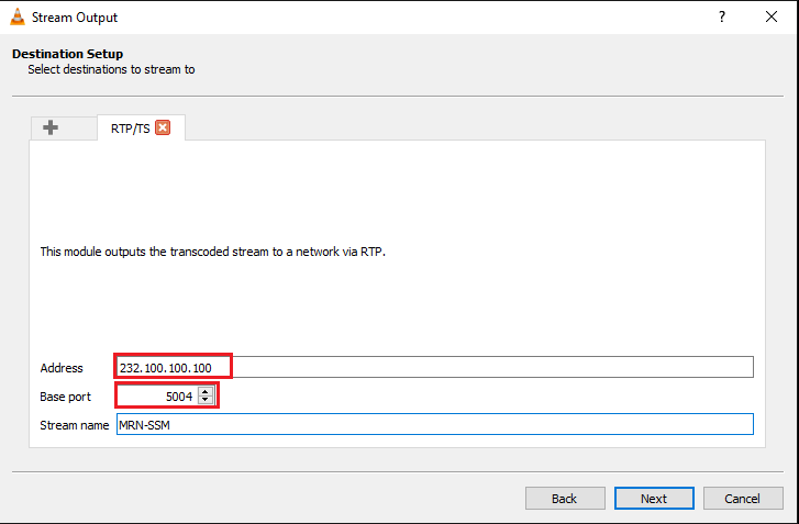
In that section you can enter your Multicast Group Addresses. I have used 232.100.100.100 and leave default UDP port 5004.
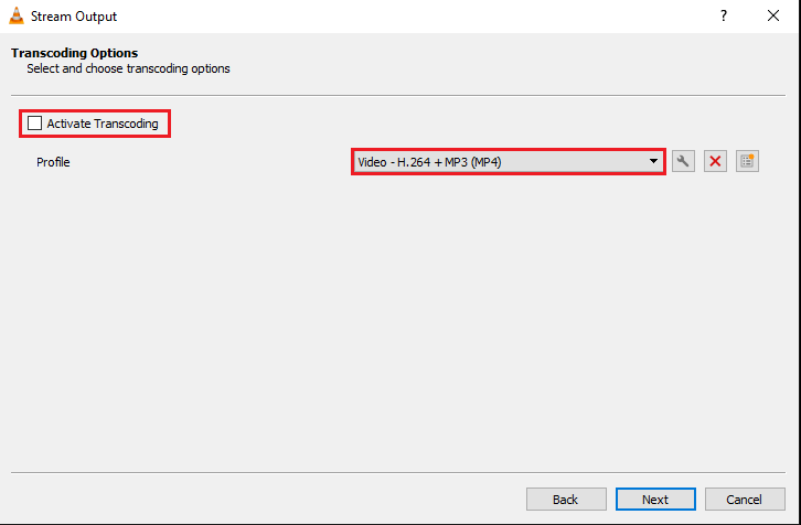
Once you click next, you will get a screen like below. You can untick “Activate Transcoding” option. Then click “Next”
In the last step, you can click “Stream” button to stream the video. You can select “stream all elementary streams” option as well.

If you monitor, Multicast source’s ethernet interface or SW2 G0/3 interface, you will see ~8 Mbps of traffic coming to that switch port.

Now you have to go to a receiver and make sure that is send IGMPv3 join msg with specific group address. You can use VLC to receive multicast traffic. You have to use “rtp://192.168.224.100@232.100.100.100:5004” format to specify the both source and group address in network URL once you go to “Media -> Open Network Stream” on your VLC player.


Now you can go to SW1 (LHR- Last Hop Router or Edge Router) and use “show ip igmp groups” & “show ip mroute” output to verify basic configurations.
SW1#sh ip igmp groups
IGMP Connected Group Membership
Group Address    Interface                Uptime    Expires   Last Reporter   Group Accounted
239.255.255.250  Vlan129                  2d09h     00:02:05  192.168.129.200
232.100.100.100  Vlan129                  00:05:09  stopped   192.168.129.200
224.0.1.40       GigabitEthernet1/0/14    4d03h     00:01:55  192.168.128.2

MRN-S1#show ip mroute
IP Multicast Routing Table
Flags: D - Dense, S - Sparse, B - Bidir Group, s - SSM Group, C - Connected,
       L - Local, P - Pruned, R - RP-bit set, F - Register flag,
       T - SPT-bit set, J - Join SPT, M - MSDP created entry, E - Extranet,
       X - Proxy Join Timer Running, A - Candidate for MSDP Advertisement,
       U - URD, I - Received Source Specific Host Report,
       Z - Multicast Tunnel, z - MDT-data group sender,
       Y - Joined MDT-data group, y - Sending to MDT-data group,
       G - Received BGP C-Mroute, g - Sent BGP C-Mroute,
       N - Received BGP Shared-Tree Prune, n - BGP C-Mroute suppressed,
       Q - Received BGP S-A Route, q - Sent BGP S-A Route,
       V - RD & Vector, v - Vector, p - PIM Joins on route,
       x - VxLAN group
Outgoing interface flags: H - Hardware switched, A - Assert winner, p - PIM Join
 Timers: Uptime/Expires
 Interface state: Interface, Next-Hop or VCD, State/Mode

(*, 239.255.255.250), 2d09h/00:02:34, RP 0.0.0.0, flags: SJC
  Incoming interface: Null, RPF nbr 0.0.0.0
  Outgoing interface list:
    Vlan129, Forward/Sparse, 2d09h/00:02:34

(192.168.224.100, 232.100.100.100), 00:18:26/00:02:28, flags: sTI
  Incoming interface: GigabitEthernet1/0/14, RPF nbr 192.168.128.1
  Outgoing interface list:
    Vlan129, Forward/Sparse, 00:07:41/00:02:28

(*, 224.0.1.40), 4d03h/00:02:29, RP 0.0.0.0, flags: DCL
  Incoming interface: Null, RPF nbr 0.0.0.0
  Outgoing interface list:
    GigabitEthernet1/0/14, Forward/Sparse, 1d11h/00:02:29
If you got to SW2 (FHR-First Hop Router) & issue “show ip mroute” you should see entry like below.
SW2#show ip mroute
(192.168.224.100, 232.100.100.100), 00:35:57/00:02:58, flags: sT
  Incoming interface: Vlan224, RPF nbr 0.0.0.0
  Outgoing interface list:
    GigabitEthernet0/6, Forward/Sparse, 00:13:27/00:02:58
Here is the R1, “show ip mroute” output
R1#show ip mroute
(192.168.224.100, 232.100.100.100), 00:26:52/00:03:11, flags: sT
  Incoming interface: GigabitEthernet0/0, RPF nbr 192.168.178.2
  Outgoing interface list:
    GigabitEthernet0/1, Forward/Sparse, 00:16:07/00:03:11

(*, 224.0.1.40), 4d03h/00:02:59, RP 0.0.0.0, flags: DPL
  Incoming interface: Null, RPF nbr 0.0.0.0
  Outgoing interface list: Null
Even everything appear to be normal, you would see, your Multicast receiver is not getting the video feed. If you take a packet capture from switchport where multicast source is connected, you will see the multicast traffic coming into SW2, however you noticed TTL value set to 1. This mean traffic will drop from that first hop router.

To fix that issue, you have to change TTL value of that traffic stream prior to hit “Stream” button. You can do that as shown below by adding higher TTL value (I used 10 for example as my network not have more than 10 hops)

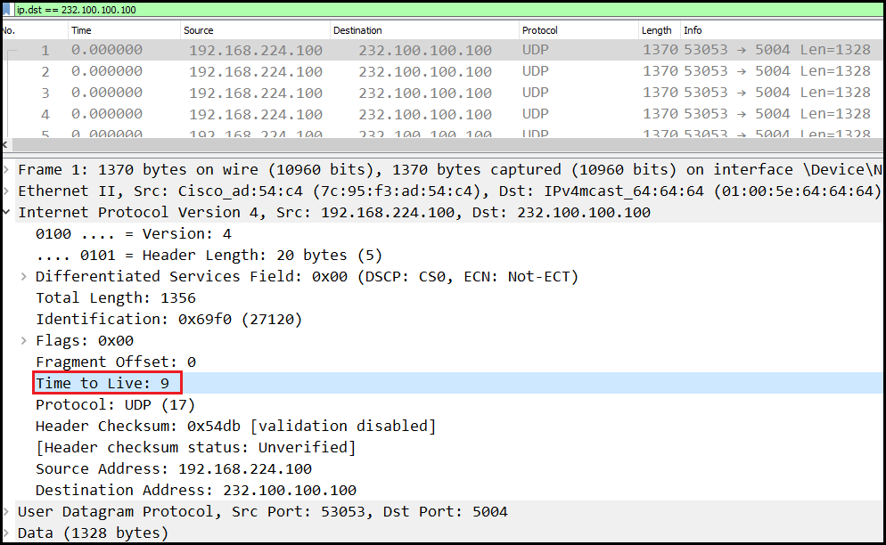
Now if you monitor traffic on G0/6 interface of SW2 you will see multicast traffic is forwarding & TTL value decrement by 1 which resulting to 9.
This time you should see your video is playing on your receiver without any trouble. Here is a short demonstration of my testing.
I would suggest you to use same multicast group address on those two servers and test that you can receive those two feeds into two receivers without having any problem. Without SSM, if you try to use same group address in different sources, receivers cannot get that two feeds as both use same group address and receivers cannot specify source of multicast source.
In any case if you still have traditional IGMPv2 only receivers, there is a way to map those IGMPv2 request to a PIM-SSM join using method called “SSM mapping” using either “static” or “DNS” method.
I hope this post helps you to re-look at your multicast configurations and see where is the complication. If you are not using PIM-SSM, then it is time to think about moving towards SSM using 3 simple steps with Cisco network devices.
- Enable IP multicast routing (ip multicast-routing)
- Enable IGMPv3 & PIM on all your interfaces (ip pim sparse-mode and ip igmp version 3)
- Enable PIM-SSM (ip pim ssm default)

Very useful post !!!
Thank a lot
Thank you Eoudart
Thanks for this explanation. How would you configure it if you had two routers and using VRFs for this?