
Tags
Let’s consider the following scenario.
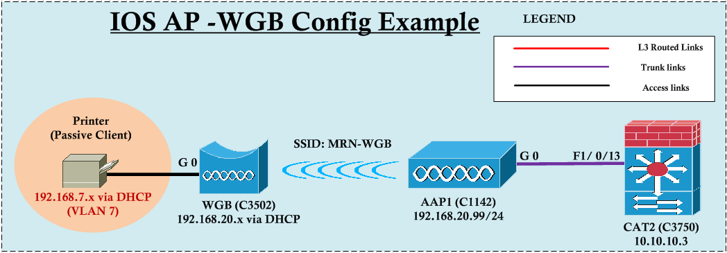
A WGB is connected to a root AP (AAP1) using EAP-FAST as security method. AAP1 is having 192.168.20.99 (Vlan20) management IP. A Printer (Passive Client) connected to WGB should get an IP from 192.168.7.0/24 (Vlan7) which is different to AAP management VLAN.
Here are few basic rules to remember when configuring WGB
1. WGB will associate to root AP using bridge-group 1 (native vlan)
2. If WGB to support multiple VLANs then it should be in “infrastructure” mode (in Unified Wirelss or WLC based WGB, this is not required)
3. If WGB itself require an IP (for mgmt purposes) it should be on native VLAN (of WGB)
Based on the above rules, Here are the two different valid options to fulfill this requirement.
Option 1:
Configure WGB to support multiple VLAN & assign all clients behind WGB to vlan 7. In this case WGB itself will take an IP from VLAN20 which is native vlan on WGB.
Option 2:
Make VLAN 7 as native on WGB while keeping AAP native VLAN to 20. In this way WGB & clients get IP from VLAN7 & no multiple VLAN support on WGB.
Since I have written a post on how to configure EAP-FAST, I will not describe the steps here simply use the configuration required, please read that post if you require more information.
Here how you could configure Option 1 as a solution for this.
In AAP1 “infrastructure-client” command under dot11 radio 0 interface make WGB “infrastructure” mode which is required to support multiple vlan on WGB.
hostname AAP1
!
aaa new-model
aaa group server radius RAD-GROUP
 server 192.168.20.99 auth-port 1812 acct-port 1813
!
aaa authentication login EAP-METHODS group RAD-GROUP
!
radius-server local
  nas 192.168.20.99 key Cisco123
  user wgb password Cisco123
!
radius-server host 192.168.20.99 auth-port 1812 acct-port 1813 key Cisco123
!
dot11 ssid MRN-WGB
   vlan 20
   authentication open eap EAP-METHODS
   authentication network-eap EAP-METHODS
   authentication key-management wpa version 2
!
interface Dot11Radio0
 encryption vlan 20 mode ciphers aes-ccm
 ssid MRN-WGB
 station-role root
 infrastructure-client
!
interface Dot11Radio0.7
 encapsulation dot1Q 7
 bridge-group 7
!
interface Dot11Radio0.20
 encapsulation dot1Q 20 native
 bridge-group 1
!
interface GigabitEthernet0.7
 encapsulation dot1Q 7
 bridge-group 7
!
interface GigabitEthernet0.20
 encapsulation dot1Q 20 native
 bridge-group 1
!
interface BVI1
 ip address 192.168.20.99 255.255.255.0
ip default-gateway 192.168.20.254
sntp server 10.10.205.20
Here is the WGB configuration looks like.”workgroup-bridge client-vlan 7” command will enforce client behind WGB to be on vlan 7. “ip address dhcp” under BVI1 interface will ensure WGB will get an IP from native vlan which is 20 to manage WGB itself. “bridge 7 address 0018.fea5.dc3e forward GigabitEthernet0.7” ensure if WGB client is “passive-client” (Printer in my case) with MAC address 0018.fea5.dc3e remain in WGB bridge table without aging-out.
hostname WGB
!
dot11 ssid MRN-WGB
   vlan 20
   authentication open eap EAP-METHODS
   authentication network-eap EAP-METHODS
   authentication key-management wpa version 2
   dot1x credentials FAST
   dot1x eap profile FAST
!
eap profile FAST
 method fast
!
dot1x credentials FAST
 username wgb
 password Cisco1123
!
interface Dot11Radio0
 encryption vlan 20 mode ciphers aes-ccm
 ssid MRN-WGB
 station-role workgroup-bridge
!
interface Dot11Radio0.7
 encapsulation dot1Q 7
 bridge-group 7
!
interface Dot11Radio0.20
 encapsulation dot1Q 20 native
 bridge-group 1
!
interface GigabitEthernet0.7
 encapsulation dot1Q 7
 bridge-group 7
!
interface GigabitEthernet0.20
 encapsulation dot1Q 20 native
 bridge-group 1
!
interface BVI1
 ip address dhcp
sntp server 10.10.205.20
!
bridge 7 address 0018.fea5.dc3e forward GigabitEthernet0.7
workgroup-bridge client-vlan 7
If you do this you can see your printer will get an IP in the range of 192.168.7.x/24 where as WGB itself will get an IP 192.168.20.x/24 range. I have configured DHCP on CAT2 for these two VLAN. Here is the CAT2 config for this example.
interface FastEthernet1/0/13
 description TEMP-AAP1-1142
 switchport trunk encapsulation dot1q
 switchport trunk native vlan 20
 switchport mode trunk
!
ip dhcp excluded-address 192.168.20.1 192.168.20.99
ip dhcp excluded-address 192.168.7.1 192.168.7.99
!
ip dhcp pool VLAN7
   network 192.168.7.0 255.255.255.0
   default-router 192.168.7.1
   domain-name mrn.com
   dns-server 192.168.200.1
!
ip dhcp pool vlan20
   network 192.168.20.0 255.255.255.0
   default-router 192.168.20.254
   dns-server 192.168.200.1
   domain-name mrn.com
You can verify this “show dot11 association” output on AAP1 & then ping these IP from CAT2
AAP1#sh dot11 ass
802.11 Client Stations on Dot11Radio0:
SSID [MRN-WGB] :
MAC Address    IP address      Device        Name            Parent         State
0018.fea5.dc3e 192.168.7.109   WGB-client    -               44d3.caaf.4343 Assoc
44d3.caaf.4343 192.168.20.143  WGB           WGB             self           EAP-Assoc

CAT2#ping 192.168.7.109
Type escape sequence to abort.
Sending 5, 100-byte ICMP Echos to 192.168.7.109, timeout is 2 seconds:
!!!!!
Success rate is 100 percent (5/5), round-trip min/avg/max = 1/4/9 ms

CAT2#ping 192.168.20.143
Type escape sequence to abort.
Sending 5, 100-byte ICMP Echos to 192.168.20.143, timeout is 2 seconds:
!!!!!
Success rate is 100 percent (5/5), round-trip min/avg/max = 1/4/9 ms
Now let’s see how to configure this in Option 2 to achieve the same outcome. In this case we will make Vlan7 on WGB as native vlan. In this way WGB clients (including WGB itself) get vlan 7 IPs. Since AAP1 has to be on vlan 20, native vlan should be 20 for the AAP1.
Here is the AAP1 configuration.
hostname AAP1
!
aaa new-model
!
aaa group server radius RAD-GROUP
 server 192.168.20.99 auth-port 1812 acct-port 1813
!
aaa authentication login EAP-METHODS group RAD-GROUP
!
radius-server local
  nas 192.168.20.99 key Cisco123
  user wgb password Cisco123
!
radius-server host 192.168.20.99 auth-port 1812 acct-port 1813 key Cisco123
!
dot11 ssid MRN-WGB
   vlan 7
   authentication open eap EAP-METHODS
   authentication network-eap EAP-METHODS
   authentication key-management wpa version 2
!
interface Dot11Radio0
 encryption vlan 7 mode ciphers aes-ccm
 ssid MRN-WGB
 station-role root
!
interface Dot11Radio0.7
 encapsulation dot1Q 7
 bridge-group 7
!
interface Dot11Radio0.20
 encapsulation dot1Q 20 native
 bridge-group 1
!
interface GigabitEthernet0.7
 encapsulation dot1Q 7
 bridge-group 7
!
interface GigabitEthernet0.20
 encapsulation dot1Q 20 native
 bridge-group 1
!
interface BVI1
 ip address 192.168.20.99 255.255.255.0
!
ip default-gateway 192.168.20.254
sntp server 10.10.205.20
Here is the WGB configuration.
hostname WGB
!
dot11 ssid MRN-WGB
   vlan 7
   authentication open eap EAP-METHODS
   authentication network-eap EAP-METHODS
   authentication key-management wpa version 2
   dot1x credentials FAST
   dot1x eap profile FAST
!
eap profile FAST
 method fast
!
dot1x credentials FAST
 username wgb
 password Cisco123
!
interface Dot11Radio0
 encryption vlan 7 mode ciphers aes-ccm
 ssid MRN-WGB
 station-role workgroup-bridge
!
interface Dot11Radio0.7
 encapsulation dot1Q 7 native
 bridge-group 1
!
interface GigabitEthernet0.7
 encapsulation dot1Q 7 native
 bridge-group 1
!
interface BVI1
 ip address dhcp
!
bridge 1 address 0018.fea5.dc3e forward GigabitEthernet0.7
!
sntp server 10.10.205.20
You can verify the Printer & WGB IP details & connectivity to rest of the network as follows.
AAP1#show dot11 associations
802.11 Client Stations on Dot11Radio0:
SSID [MRN-WGB] :
MAC Address    IP address      Device        Name            Parent         State
0018.fea5.dc3e 192.168.7.109   WGB-client    -               44d3.caaf.4343 Assoc
44d3.caaf.4343 192.168.7.112   WGB           WGB             self           EAP-Assoc

CAT2#ping 192.168.7.109
Type escape sequence to abort.
Sending 5, 100-byte ICMP Echos to 192.168.7.109, timeout is 2 seconds:
!!!!!
Success rate is 100 percent (5/5), round-trip min/avg/max = 1/4/9 ms

CAT2#ping 192.168.7.112
Type escape sequence to abort.
Sending 5, 100-byte ICMP Echos to 192.168.7.112, timeout is 2 seconds:
!!!!!
Success rate is 100 percent (5/5), round-trip min/avg/max = 1/2/9 ms
.
Related Posts
1. WGB Configuration
2. WGB with EAP-FAST
3. WGB with CAPWAP
4. WGB with PSK
5. WGB Roaming
6. IOS AP-WGB with Multiple VLAN
7. Unified AP-WGB with Multiple VLAN
8. Packet Retries & Max-Retries
9.

As always the post is well written and informative!
Thanks Prasanna…
Could you please explain one thing:
Why on the switchport, connected to the root ap is not configured vlan 7 as allowed?
if you haven’t configure “sw tr al vlan x” command imply you are allowing all the vlans (1-4094) across that trunk.
If you want only certain vlan to pass, then you can use that command and restrict which vlan to allow. In my case I left it as default all vlans.
HTH
Rasika
Hi Navarasi,
Thank you very much for the great resource and explanations you managed to put no your blog, it’s awesome, I can guarantee you that I’m learning a lot from you, you will be my master in wireless, you congrats you when I pass my lab if God helps me in April.
Hi Anderson,
Thanks for your kind appreciation.
I am sure you will be getting your CCIEW, do not give up & keep working on it until you get it..It is doable…
Rasika
Hi Rasika,
if AAP1/WGB has only one(1) vlan, is it recomended to do sub-interface+dot1q for single vlan anyway?
Thanks
JT
NO, then go with main interfaces without creating sub-interfaces
HTH
Rasika
Thank you.
hello rasika,
a question please: in your example above, if the printer is directly connected to the WGB, then what should be the configuration for the gig interface on the WGB?
I understand that we only care about assigning the gig interface to bridge-group 7?
Can you please explain?
Thanks
Is it possible to keep dhcp server in the WGB area, will it supports in leasing ip address to clients connected to RAP/WLC?
Hello,
Someone took a problem that o IR829 the router stop of answer on the network, but the AP803 continue work normaly, I’m with this issues at my envirioment the WLC currently is 9800.